Router

a router and routing technology, applied in the field of bits, can solve the problems of inefficiency of the process of changing bits with multiple hands, hazard to those working near the tool, and poor tool performance, and achieve the effect of overturning the bias for

Active Publication Date: 2010-08-19
BLACK & DECKER INC
View PDF33 Cites 5 Cited by
  • Summary
  • Abstract
  • Description
  • Claims
  • Application Information

AI Technical Summary

Benefits of technology

[0009]The present invention is directed to a bit retaining system for a rotary tool such as a router. In one embodiment, the bit retaining system includes a collet assembly and a control assembly. The collet assembly includes a spindle, a collet mounted in the spindle that is adapted to receive a bit, and a collet nut that alters the internal dimensions of the collet to capture the bit therein. The collet assembly may further include a collet gear mounted on the collet nut and / or a spindle gear mounted on the spindle. The control assembly selectively engages the collet assembly to drive the collet nut relative to the spindle. In operation, a hand tool is utilized to engage the control assembly. A bias member biases an engagement portion of the control assembly away from the collet assembly. However, the engagement portion is engaged with the collet assembly when the user urges the tool to overcome the bias force. A turning force is simultaneously applied to the urging force to cause relative rotation of the spindle and collet nut. This configuration enables a user to capture and release the rotary tool bit using one hand.

Problems solved by technology

Otherwise, the bit will slip in its holder, resulting in poor tool performance, as well as creating a hazard to those working near the tool.
This process of utilizing multiple hands for changing the bits is inefficient and thus undesirable because of the additional time and effort required for attaching the bits to and removing the bits from the collet.
This use of conventional wrenches to displace the collet nut is not only cumbersome, but often proves ineffective since the effective clamping force is dependent on the torque applied by the individual operator, which varies from one person to another.

Method used


Image

  • Router
  • Router
  • Router

Examples


Embodiment Construction

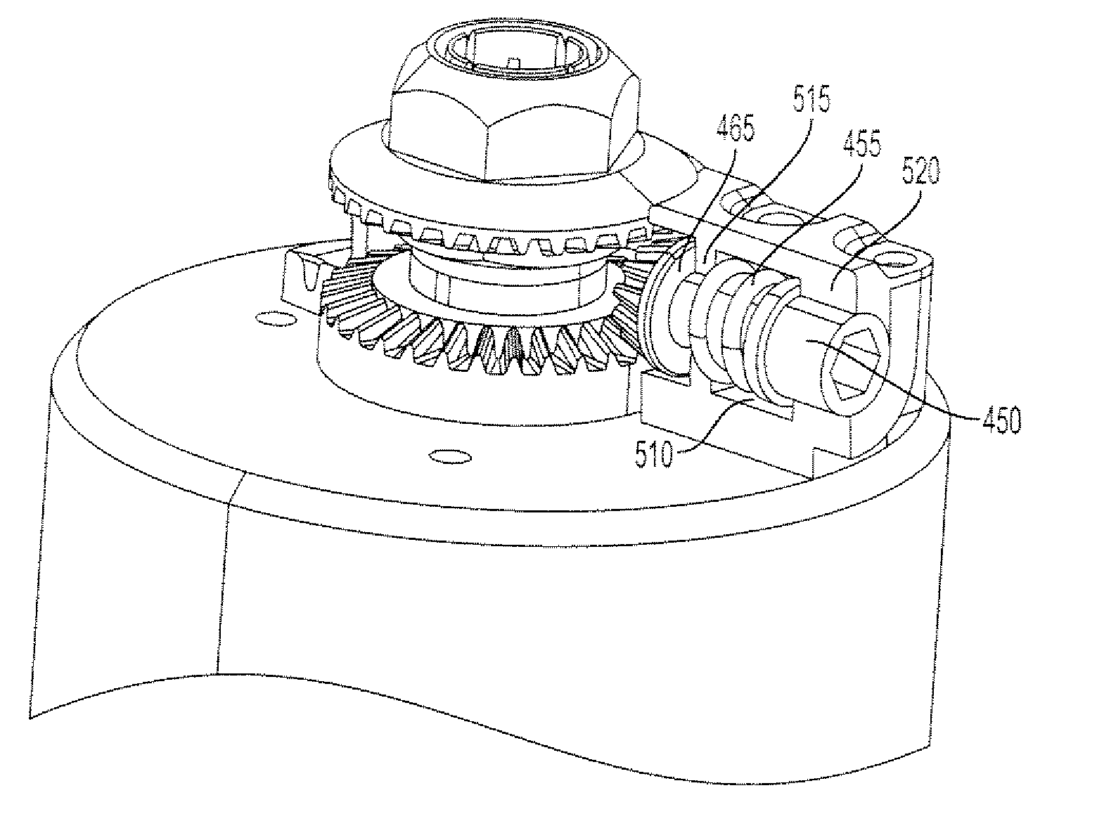
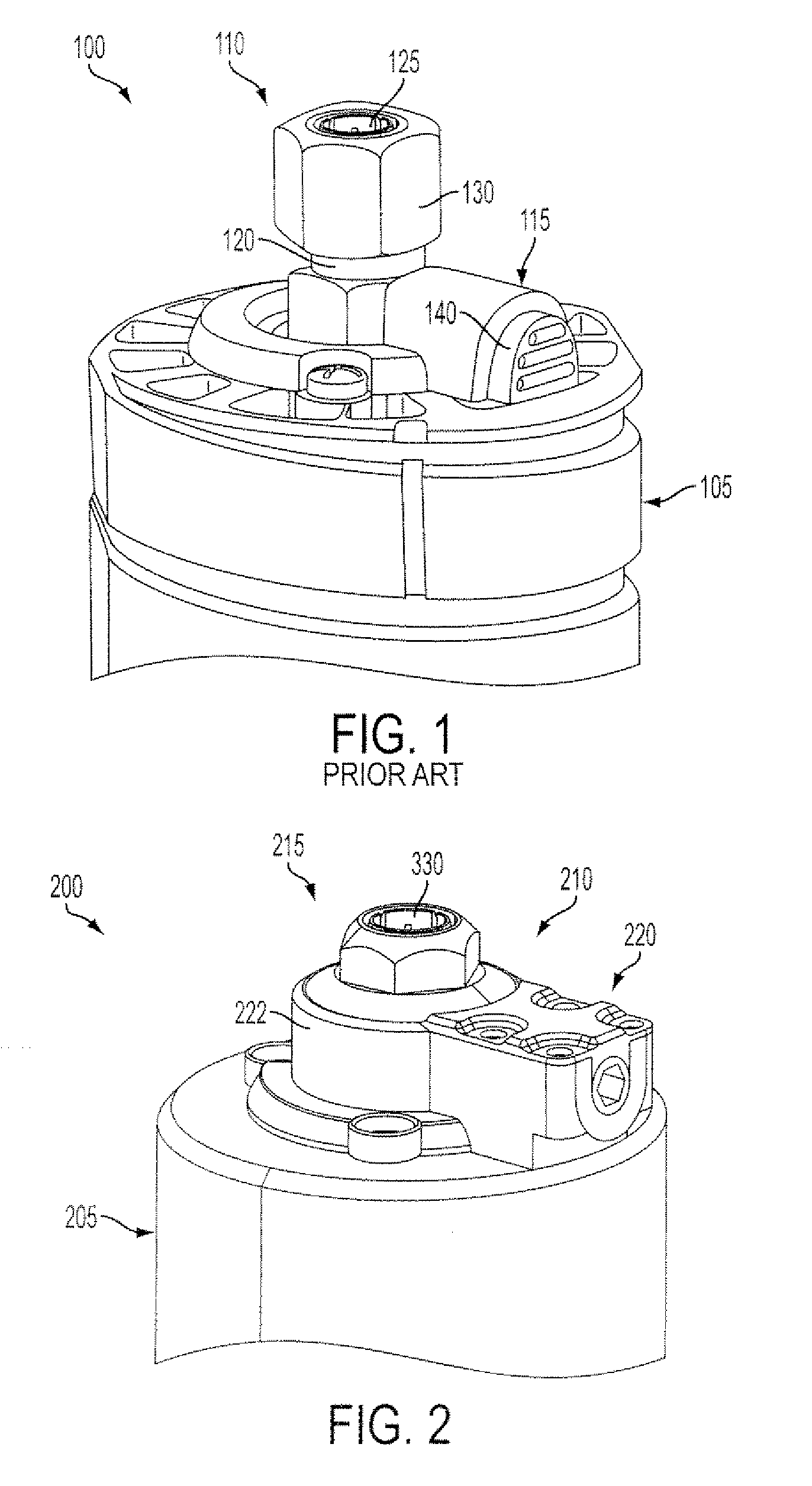
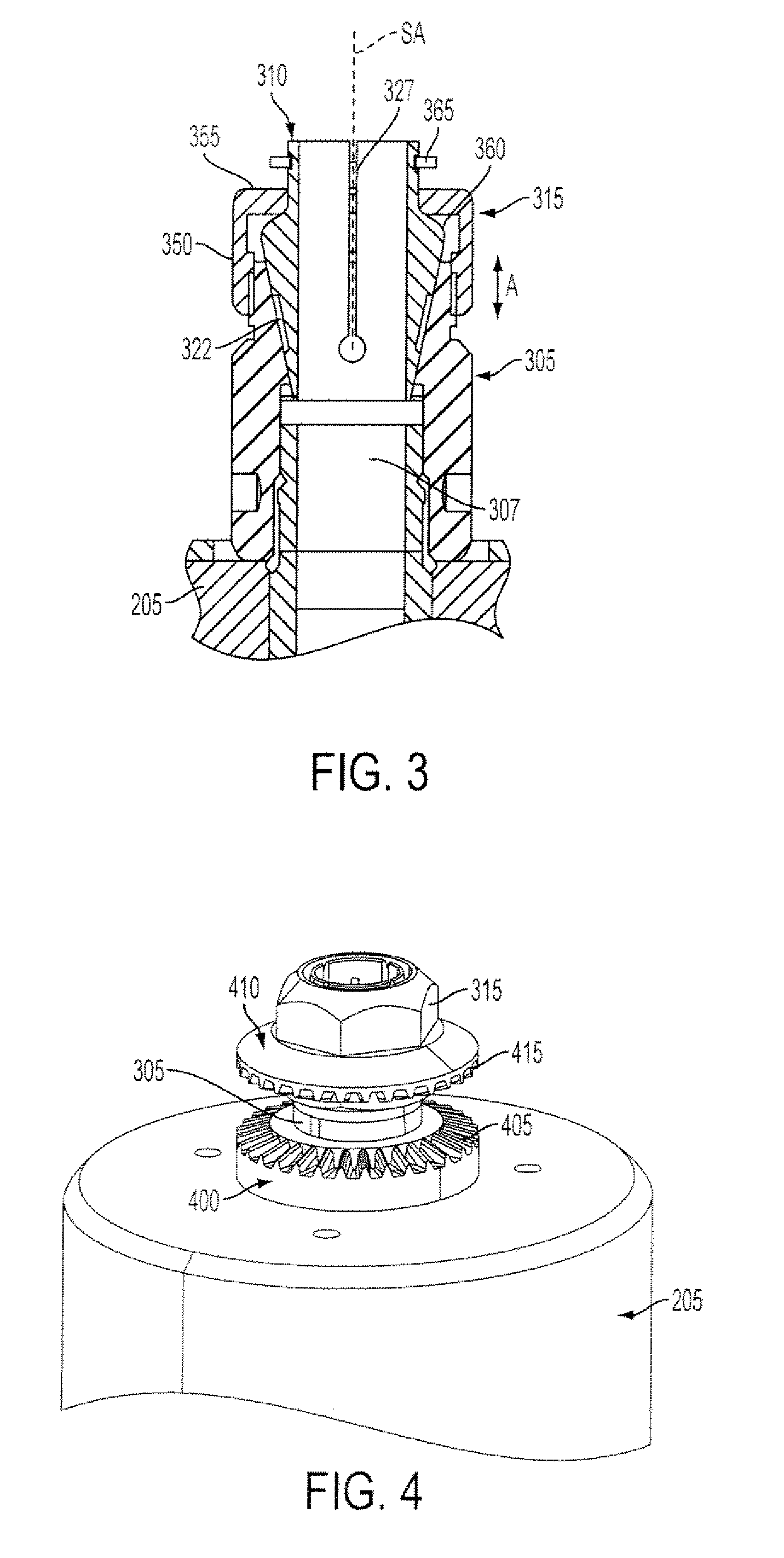
[0028]FIGS. 2 and 3 illustrate a rotary tool including a bit retaining system in accordance with an embodiment of the present invention. Referring to FIG. 2, the rotary tool 200 (e.g., a router) with a motor housing 205 and a bit retaining system 210 including a collet assembly 215 in selective communication with a control assembly 220 disposed in a system housing 222. Referring to FIG. 3, the collet assembly 215 includes a spindle 305, a collet 310, and collet nut 315. The spindle 305, which may generally define a right cylinder, extends distally from the motor housing 205 from a generally centrally location thereon. The distal portion of the spindle 305 is externally threaded to engage complementary threads on the collet nut 315.

[0029]The spindle 305 defines an interior channel 322 that tapers radially inward in the direction of the motor housing 205 to define a spindle channel having a generally frustoconical shape. The collet 310 is received in the channel 322 such that it is ge...


PUM

PropertyMeasurementUnit
rotationaaaaaaaaaa
rotationaaaaaaaaaa
rotary forceaaaaaaaaaa

Abstract

A bit retaining system for a rotary tool or device such as a router is disclosed. The bit retaining system may include a collet assembly and a control assembly. The collet assembly may include a spindle, a collet adapted to receive the bit, and a collet nut. The collet assembly may further include a collet gear mounted on the collet nut and / or a spindle gear mounted on the spindle. The control assembly selectively engages the collet assembly to drive the collet nut and / or secure the spindle in a fixed position, preventing its rotation. In operation, a hand tool is utilized to engage the control assembly. This configuration enables a user to capture and release the rotary tool bit using one hand.

Description

CROSS REFERENCE TO RELATED APPLICATIONS[0001]This application claims priority to U.S. Provisional Patent Application No. 61 / 207,675, filed on 13 Feb. 2009 and entitled “Router”, the disclosure of which is hereby incorporated by reference in its entirety.FIELD OF THE INVENTION[0002]The present invention is directed toward a system for releasably securing a cutting tool to a rotary device and, in particular, to a bit retaining system that secures a bit to a router.BACKGROUND OF THE INVENTION[0003]Rotary tools, such as drills or routers, include a tool retainer or holder that non-rotatably secures a rotary bit (e.g., a cutting tool such as a drill bit or a router bit) to a driving device that rotates a drive shaft. The rotation of the drive shaft causes a corresponding rotation of the rotary bit; consequently, the clamping force of the retainer must provide sufficient gripping action of the bit. Otherwise, the bit will slip in its holder, resulting in poor tool performance, as well as ...

Claims


Application Information

Patent Timeline
Patent Type & Authority Applications(United States)
IPC IPC(8): B23C5/26B23B31/20B23C9/00B23Q3/12
CPCB23B31/201Y10T279/17504B23B2260/07B23B31/20B23B2231/2083Y10T408/953Y10T279/17299Y10T279/3431Y10T279/32Y10T409/306608Y10T279/27Y10T409/309408Y10T408/04Y10T279/3451B23B2231/2081B23B31/20125B27C5/10B23B45/006B25B33/005B23C1/20B23B2260/078
Inventor CEROLL, WARREN A.GRIFFIN, GREGORY K.MCDANIEL, STEVEN D.SCHELL, CRAIG A.GEHRET, ROBERT S.KELLEHER, JOSEPH P.
Owner BLACK & DECKER INC
Why Eureka
Try Eureka