Positionable connector assembly

a connector and assembly technology, applied in the direction of safety belts, life-saving devices, buckles, etc., to achieve the effect of reducing the friction of the connector

Active Publication Date: 2022-06-28
PURE SAFETY GRP INC
View PDF31 Cites 4 Cited by
  • Summary
  • Abstract
  • Description
  • Claims
  • Application Information

AI Technical Summary

Benefits of technology

[0008]In one embodiment method of positioning a connector of a connector assembly, the connector assembly includes a base, the connector is operatively connected to the base, a friction member is positioned between the base and the connector, and a biasing member is operatively connected to the connector and is configured and arranged to bias the connector toward the friction member. The connector is contacted and moved relative to the base to one of several positions, wherein a biasing force of the biasing member is overcome thereby reducing an amount of friction on the connector thereby allowing the connector to move. Once in the one of several position, the connector is released, wherein the biasing force biases the connector toward the friction member thereby holding the connector in the one of several positions relative to the base.

Problems solved by technology

To connect and disconnect the lifeline or lanyard, it may be difficult if the D-ring is in a downward position relative to the user.

Method used


Image

  • Positionable connector assembly
  • Positionable connector assembly
  • Positionable connector assembly

Examples


Embodiment Construction

[0021]In the following detailed description, reference is made to the accompanying drawings, which form a part hereof, and in which is shown by way of illustration embodiments in which the disclosure may be practiced. It is to be understood that other embodiments may be utilized and mechanical changes may be made without departing from the spirit and scope of the present disclosure. The following detailed description is, therefore, not to be taken in a limiting sense.

[0022]Embodiments of the disclosure provide a positionable connector assembly.

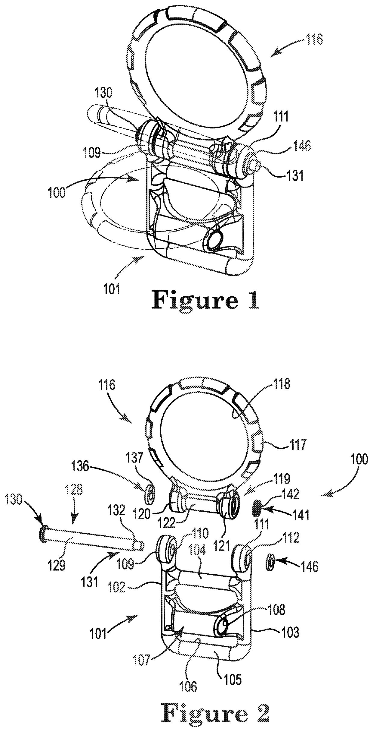
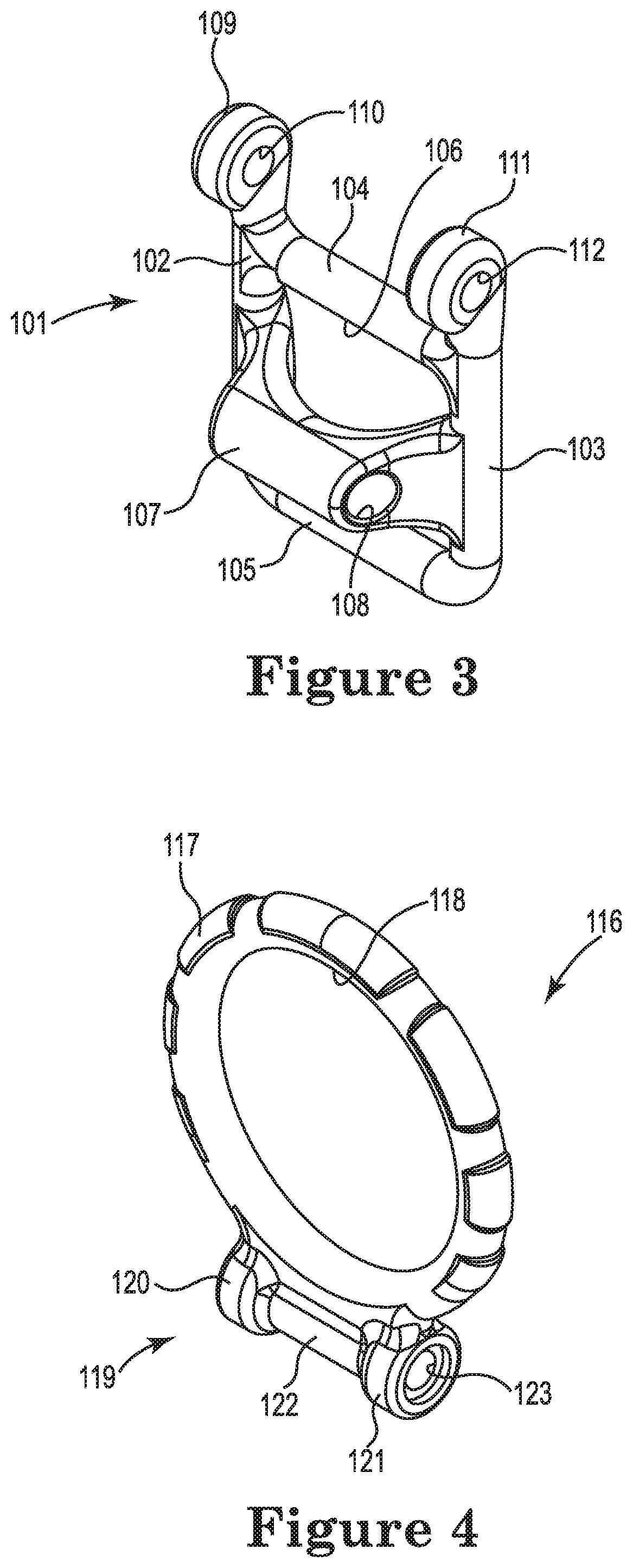
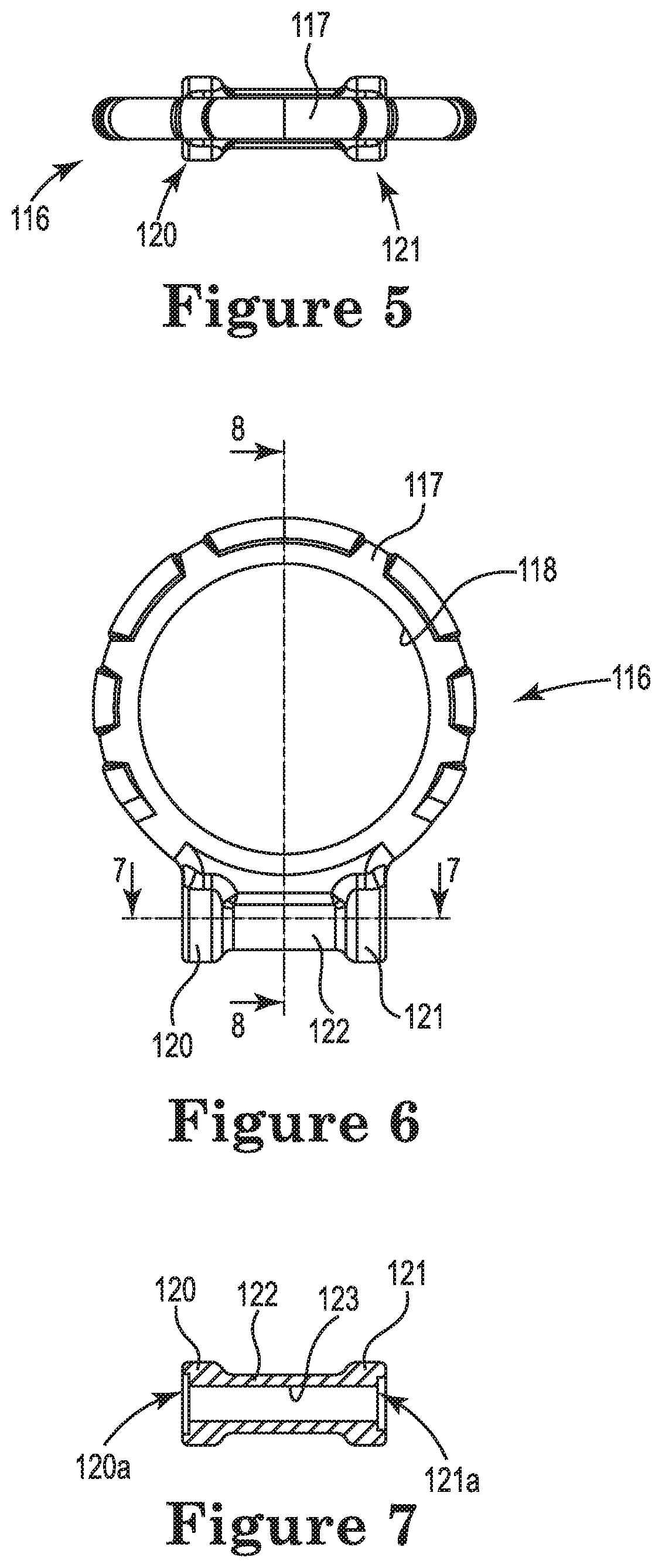
[0023]An example embodiment is illustrated in FIGS. 1-2. A positionable connector assembly 100 includes a base 101 to which a connector 116 is connected. Generally, the positionable connector assembly 100 could be connected to straps of a safety harness proximate a user's back or other desired locations. It is recognized that any suitable base could be used and any suitable connector such as a D-ring could be used. Throughout the description, ...


PUM


Abstract

A positionable connector assembly comprises a base, a connector operatively connected to the base, a friction member positioned between the base and the connector, and a biasing member operatively connected to the connector and configured and arranged to bias the connector toward the friction member.

Description

[0001]This application claims the benefit of U.S. Provisional Patent Application 62 / 662,809, filed Apr. 26, 2018, incorporated by reference herein.BACKGROUND[0002]Fall protection equipment is commonly used to reduce a likelihood of a fall and / or injuries associated with a fall, particularly by users who perform tasks at heights or are at risk of falling. Generally, lifelines or lanyards typically interconnect anchorage structures and safety harnesses donned by users. The lifelines or lanyards allow the users to move and perform tasks while being connected to the anchorage structures. Should a user fall, the lifeline or lanyard limits the distance the user falls.[0003]A user often connects a lifeline or a lanyard to a dorsal D-ring positioned on the back of the user's safety harness. To connect and disconnect the lifeline or lanyard, it may be difficult if the D-ring is in a downward position relative to the user. There are other positions on the safety harness where a positionable D...

Claims


Application Information

Patent Timeline
Patent Type & Authority Patents(United States)
IPC IPC(8): A62B35/00
CPCA62B35/0037A44B11/00
Inventor CARRASCA, ROBERT G.HAMLIN, CHRISTOPHER ROSSPIPER-KAISER, DYLAN JAMESCRABB, KATHRYN ROSE
Owner PURE SAFETY GRP INC
Why Eureka
Try Eureka