Double Acting Fluid Pump

a fluid pump and double-action technology, applied in the field of fluid pumps, can solve the problems of large spikes in fluid pressure at the output valve, increase undesirable vibration and noise, and reduce the maximum pressure spike. , the effect of increasing the volume of the secondary chamber

Active Publication Date: 2012-02-09
PROVIDENCE ENTERPRISE LTD
View PDF8 Cites 8 Cited by
  • Summary
  • Abstract
  • Description
  • Claims
  • Application Information

AI Technical Summary

Benefits of technology

[0008]The fluid pump has first and second pistons that are fixedly attached to a common shaft. The first and second pistons are of different sizes so that its volumetric linear displacement is different. In the example shown herein, the first piston is smaller than the second piston so that for every incremental linear displacement of the first piston, a smaller volume is displaced in comparison to the volumetric displacement of the second piston. During operation of the fluid pump, a secondary chamber decreases during a suction stroke thereby pumping fluid out of an outlet of the fluid pump. During a compression stroke, the volume of the secondary chamber increases. Nonetheless, fluid is pumped out of the outlet. The way that this is accomplished is by incorporating a one-way valve in the second piston. During the compression stroke, the one-way valve is opened to provide fluid communication between the secondary chamber and a pumping chamber. Although the volume of the secondary chamber increases during the compression stroke, the cumulative volume of the secondary chamber and the pumping chamber decreases to pump fluid out of the pump. The volumes of the secondary and pumping chambers are cumulated since the one-way valve is open and provides fluid communication therebetween. Hence, during the compression stroke, fluid is pumped out of the pump. The pump pumps fluid during both the compression and suction strokes. Since fluid is pumped out of the pump during both the compression and suction strokes, fluid flow rate at the output of the pump may be spread over a longer period of time which provides for lower maximum pressure spikes at the output valve compared to prior art pumps which discharge fluid only during the compression stroke.
[0009]Moreover, the compression and suction strokes may be aided by fluid pressure. In particular, the outlet of the fluid pump may always be pressurized. This places positive pressure in the secondary chamber. When the one-way valve disposed on the second piston is in the closed position, the fluid pressure applies a force on the second piston as well as on the first piston. However, since the second piston is larger than the first piston (i.e., larger surface area), the net bias force due to fluid pressure provides a fluid pressure bias force to initiate the compression stroke. As the compression stroke progresses, the pressure within the pumping chamber increases which ultimately opens up the one-way valve on the second piston. The fluid pressure does not create a force on the second piston at this time. Nonetheless, when the one-way valve opens up, the first piston is sufficiently disposed within the solenoid so that the power of the solenoid can drive the rest of the compression stroke without the fluid pressure bias force. At the end of the compression stroke, the pumping chamber is slightly pressurized which aids in initiating the suction stroke. Additionally, the pressure at the outlet of the fluid pump may aid in suction stroke. In particular, the pressure at the outlet of the fluid pump acts on the second piston since the one way valve is closed at this point. The fluid pressure produces a fluid pressure bias force on the second piston. The spring must overcome this fluid pressure bias force acting on the second piston. Fortunately, the pressure at the outlet of the fluid pump is also applied to the first piston and produces a fluid pressure bias force on the first piston in the opposite direction. This fluid pressure bias force on the first piston counteracts the fluid pressure bias force on the second piston so that a weaker spring may be utilized. The spring is aided by the fluid pressure applied to the first piston to overcome the fluid pressure bias force on the second piston. A smaller spring also allows use of a weaker solenoid to drive the suction stroke. Fluid pressure at the pump outlet is used to assist the compression and suction strokes to reduce the size requirements of the solenoid and spring. Weaker springs and solenoids may be used which reduces the operating temperature of the fluid pump and reduces the noise and vibration of the fluid pump.
[0012]The one-way valve is closed during the suction stroke to discharge fluid out of the outlet and the one-way valve is opened during the compression stroke so that collectively the pumping chamber and the secondary chamber reduces in volume to discharge fluid out of the outlet.

Problems solved by technology

Unfortunately, these adjustments produce large spikes in fluid pressure at the output valve 22 since fluid flows out of the fluid pump only during the compression stroke.
Unfortunately, this adjustment increases undesirable vibration and noise.

Method used


Image

  • Double Acting Fluid Pump
  • Double Acting Fluid Pump
  • Double Acting Fluid Pump

Examples


Embodiment Construction

[0023]As used herein, the term “pump” refers to a device that displaces or pumps liquid or gas. Additionally, as used herein, the term “fluid” refers to liquid or gas such as air.

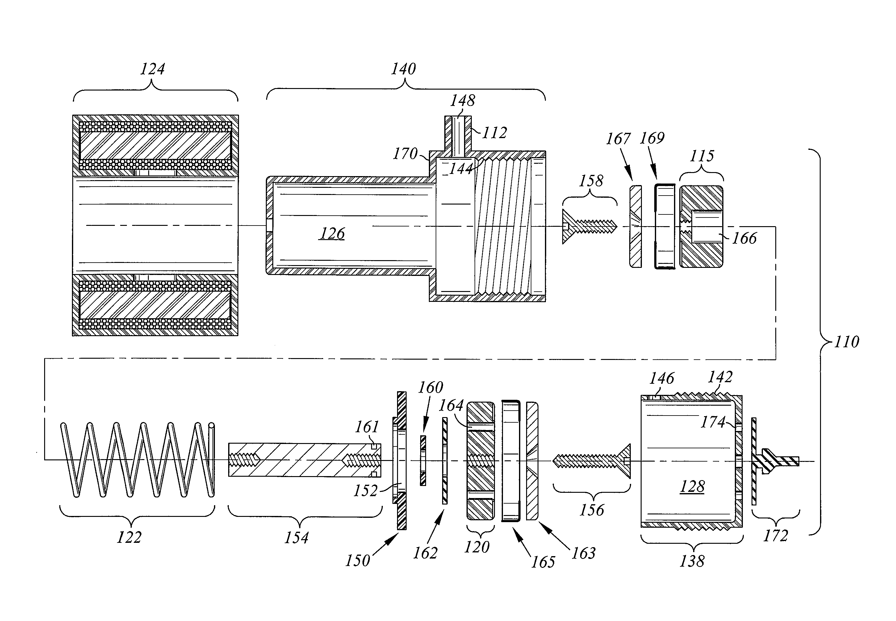
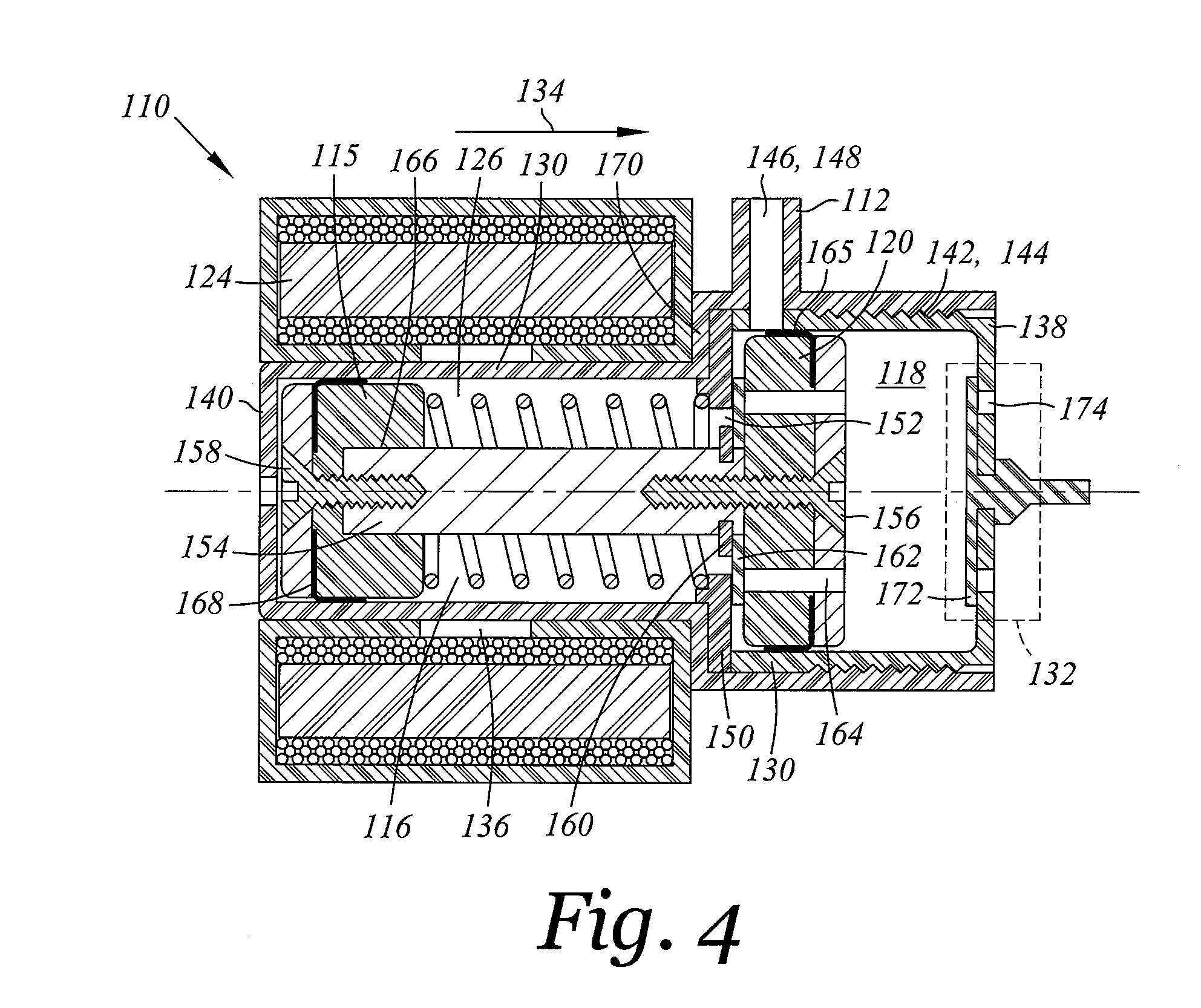
[0024]Referring now to FIGS. 4-6, a double acting dual stroke fluid pump 110 is shown. The pump 110 pumps fluid out of an outlet 112 during a compression stroke shown in FIG. 5 as well as during a suction stroke shown in FIG. 6. During the compression stroke, a one-way valve 114 is opened so that as a first piston 116 (see FIG. 5) is displaced, the cumulative volume of a secondary chamber 116 and a pumping chamber 118 is reduced thereby pumping fluid out of outlet 112. During the suction stroke shown in FIG. 6, the one-way valve 114 is closed isolating the secondary chamber 116 from the pumping chamber 118 so that the volume of the secondary chamber 116 is reduced thereby pumping fluid out of the outlet 112. The fluid pump 110 discharges fluid during both the compression and suction strokes so that a more e...


PUM


Abstract

A double acting dual stroke fluid pump with pressure assists is disclosed. First and second pistons are mounted to a common shaft which reciprocates during compression and suction strokes. During each of the strokes, fluid is pumped out at an outlet. This is accomplished by way of a one-way valve on the second piston. The one-way valve is opened or closed depending on whether the first and second pistons are in the compression or suction strokes. Additionally, pressure from the outlet assists in traversing the first and second pistons in the compression stroke. During the suction stroke, the fluid pressure applies a force on the first piston to counteract the fluid pressure on the second piston so that a smaller spring may be used. The size requirements of the solenoid and spring are reduced. Additionally, the fluid pump provides lower pressure spikes compared to prior art fluid pumps since fluid is pumped out during both the compression and suction strokes and also provides a more even flow of fluid out of the fluid pump.

Description

CROSS-REFERENCE TO RELATED APPLICATIONS[0001]Not ApplicableSTATEMENT RE: FEDERALLY SPONSORED RESEARCH / DEVELOPMENT[0002]Not ApplicableBACKGROUND[0003]The present invention relates to a fluid pump.[0004]A prior art fluid pump 10 is shown in FIGS. 1-3. FIG. 1 illustrates the prior art fluid pump 10 which includes a solenoid 12, a spring 14, and a piston 16 within a cylinder 18. Intake and output valves 20, 22 are located on the cylinder 18 which pumps fluid (e.g., liquid and gas) out of the pump 10. During the compression stroke shown in FIG. 1, the solenoid 12 is de-energized and the spring 14 traverses the piston 16 in the direction of arrow 17. Fluid is forced out of the output valve 22. At the end of the compression stroke, the solenoid 12 is energized so as to overcome the force of the spring 14 and retract the piston 16 in the direction of arrow 19 as shown in FIG. 2. Retraction of the piston 16 enlarges the pumping chamber 24 and draws fluid into the pumping chamber 24 through t...

Claims


Application Information

Patent Timeline
Patent Type & Authority Applications(United States)
IPC IPC(8): F04B53/00
CPCF04B3/00F04B1/124F04B53/102F04B53/12F04B17/046
Inventor DU, BENJAMIN R.
Owner PROVIDENCE ENTERPRISE LTD
Why Eureka
Try Eureka