Antenna apparatus provided with electromagnetic coupling adjuster and antenna element excited through multiple feeding points

an antenna element and electromagnetic coupling technology, which is applied in the field of antenna elements excited through multiple feeding points, can solve the problems of complex structure, inability of mobile radio apparatus inability to simultaneously implement a plurality of states, etc., and achieves low correlation, simple configuration, and reduced the number of antenna elements

Active Publication Date: 2008-06-19
PANASONIC INTELLECTUAL PROPERTY CORP OF AMERICA
View PDF10 Cites 50 Cited by
  • Summary
  • Abstract
  • Description
  • Claims
  • Application Information

AI Technical Summary

Benefits of technology

[0021]As described above, according to the antenna apparatus and wireless communication apparatus of the present invention, an antenna apparatus and a wireless communication apparatus can be provided that are capable of simultaneously transmitting and / or receiving a plurality of radio signals with low correlation to each other, while having a simple configuration.
[0022]According to the present invention, while reducing the number of antenna elements to one, it is possible to excite this antenna element as multiple antenna portions, and also to ensure isolation between these multiple antenna portions. The most important effects provided by the present invention include that the isolation between multiple antenna portions is ensured even when exciting a single antenna element through a plurality of feeding points simultaneously so that the antenna element operates as the multiple antenna portions; that the correlation coefficient between radio signals (electromagnetic waves) transmitted and / or received by the respective antenna portions can be reduced because the radio signals transmitted and / or received by the respective antenna portions have different polarizations; and that no degeneration occurs even when the antenna element has a symmetric structure, because different feeding methods (current feeding and voltage feeding) are used; and accordingly, each antenna portion operates well.
[0023]According to the antenna apparatus and wireless communication apparatus of the present invention, the isolation between the antenna portions can be improved, by further including an electromagnetic coupling adjuster.

Problems solved by technology

The antenna device disclosed in PCT International Publication WO02 / 39544 can switch over to a different directivity, however, this antenna device cannot simultaneously implement a plurality of states, each having a different directivity.
The mobile radio apparatus disclosed in Japanese Patent Laid-Open Publication No. 2005-130216 requires a plurality of antenna elements (flat conductors), and results in a complicated structure.
Furthermore, in a similar manner to that of the antenna device disclosed in PCT International Publication WO02 / 39544, although this mobile radio apparatus can switch over to a different directivity, this mobile radio apparatus cannot simultaneously implement a plurality of states, each having a different directivity.
The portable radio unit disclosed in PCT International Publication WO01 / 97325 cannot switch between directivities, and also cannot simultaneously implement a plurality of states, each having a different directivity.

Method used


Image

  • Antenna apparatus provided with electromagnetic coupling adjuster and antenna element excited through multiple feeding points
  • Antenna apparatus provided with electromagnetic coupling adjuster and antenna element excited through multiple feeding points
  • Antenna apparatus provided with electromagnetic coupling adjuster and antenna element excited through multiple feeding points

Examples


first preferred embodiment

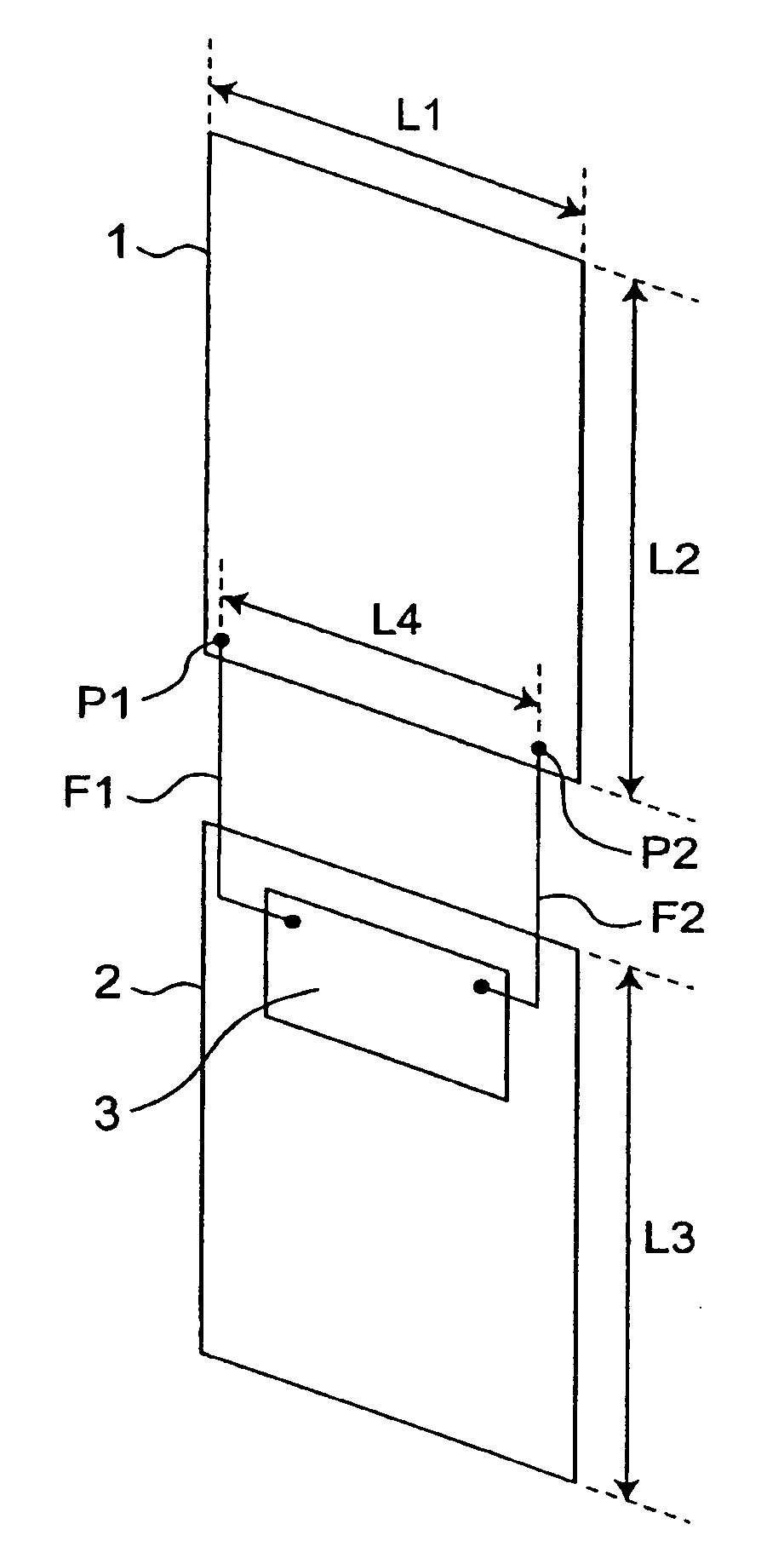
[0077]FIG. 1 is a perspective view showing a schematic configuration of an antenna apparatus according to a first preferred embodiment of the present invention. The antenna apparatus of the present preferred embodiment is characterized in that it includes a rectangular antenna element 1 having two different feeding points P1 and P2, and makes the single antenna element 1 operate as two antenna portions, by exciting the antenna element 1 as a first antenna portion through the feeding point P1, and at the same time, exciting the antenna element 1 as a second antenna portion through the feeding point P2.

[0078]In FIG. 1, the antenna apparatus includes the antenna element 1 made of a rectangular conductive plate with a horizontal length L1×a vertical length L2, and a ground conductor 2 made of a rectangular conductive plate with a horizontal length L1×a vertical length L3. The antenna element 1 and the ground conductor 2 are juxtaposed to be spaced from each other by a certain distance, ...

second preferred embodiment

[0087]FIG. 6 is a perspective view showing a schematic configuration of an antenna apparatus according to a second preferred embodiment of the present invention. Although in the antenna apparatus of the first preferred embodiment the radio signal is directly fed to the antenna element 1 at both of the feeding points P1 and P2, the antenna apparatus of the second preferred embodiment is characterized by that a radio signal is capacitively fed (fed through a capacitor) to a antenna element 1 at one of the feeding points P1 and P2 in FIG. 1, i.e., at a feeding point P1.

[0088]In FIG. 6, the antenna apparatus is provided with an electrode E1, which is made of a conductive plate and provided in parallel to an antenna element 1 at a position where the feeding point P1 is provided in FIG. 1. The electrode E1 is spaced from the antenna element 1 by a certain distance L11 through air or a certain dielectric material. Thus, in the antenna apparatus of the present preferred embodiment, a capaci...

third preferred embodiment

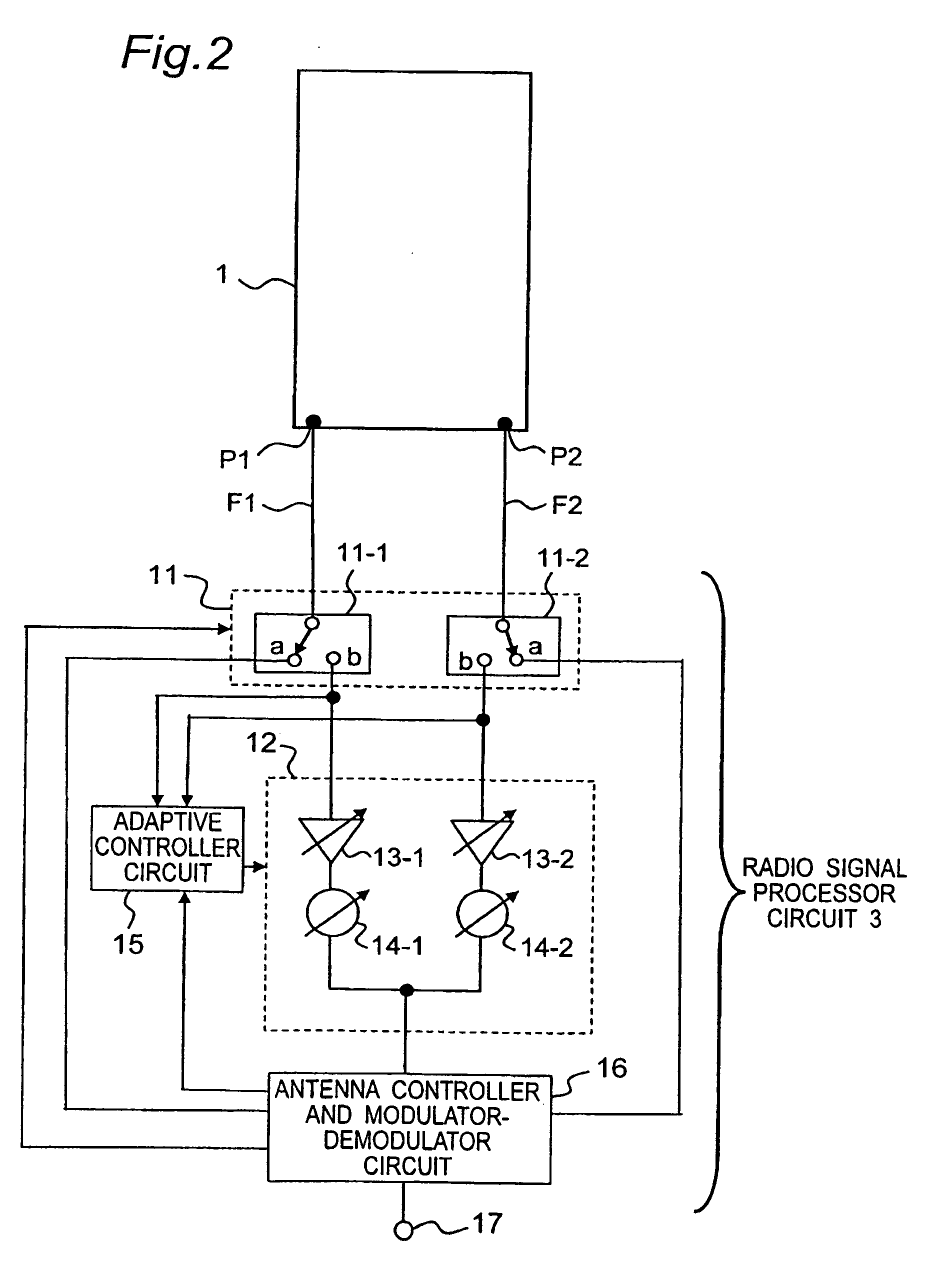
[0095]FIG. 10 is a perspective view showing a schematic configuration of an antenna apparatus according to a third preferred embodiment of the present invention, and FIG. 11 is a block diagram showing a detailed configuration of a circuit of the antenna apparatus in FIG. 10. Although in the antenna apparatus of the second preferred embodiment the antenna element 1 operates as an electric current antenna (i.e., an antenna in which the antenna element 1 acts as an electric current source) in each of both cases in which the radio signal is capacitively fed to the antenna element 1 through the feeding point P1 and in which the radio signal is fed directly to the antenna element 1 through the feeding point P2, the antenna apparatus of the third preferred embodiment is characterized in that the antenna apparatus further has a slit S1, and when a radio signal is fed to the slit S1 through a feeding point P2, the slit S1 is made to operate as a magnetic current antenna (i.e., an antenna in ...


PUM


Abstract

An antenna apparatus includes a first feeding point and a second feeding point provided at respective positions on an antenna element. The antenna element is excited through the first and second feeding points simultaneously so as to operate as a first antenna portion and a second antenna portion simultaneously, the first antenna portion and the second antenna portion correspond to the first and second feeding points, respectively. The antenna element further includes, between the first and second feeding points, an electromagnetic coupling adjuster for making an amount of isolation between the first and second antenna portions.

Description

BACKGROUND OF THE INVENTION[0001]1. Field of the Invention[0002]The present invention relates to an antenna apparatus provided with a single antenna element which is excited through a plurality of feeding points, and with an electromagnetic coupling adjuster, and relates to a wireless communication apparatus including this antenna apparatus. More particularly, the present invention relates to an antenna apparatus, e.g., for mobile communication, and relates to a wireless communication apparatus including this antenna apparatus.[0003]2. Description of the Related Art[0004]The size and thickness of portable wireless communication apparatuses, such as mobile phones, have been rapidly reduced. Portable wireless communication apparatuses have been transformed from apparatuses to be used only as conventional telephones, to data terminals for transmitting and receiving electronic mails and for browsing web pages of WWW (World Wide Web). Further, since the amount of information to be handle...

Claims


Application Information

Patent Timeline
Patent Type & Authority Applications(United States)
IPC IPC(8): H01P5/18H01Q1/24H01Q5/10
CPCH01Q1/243H01Q3/2605H01Q9/04H01Q3/36H01Q3/28
Inventor IWAI, HIROSHIYAMAMOTO, ATSUSHISAKATA, TSUTOMUAMARI, SATORU
Owner PANASONIC INTELLECTUAL PROPERTY CORP OF AMERICA
Why Eureka
Try Eureka