Processing cell of automatic machining system and automatic honing system

a technology of automatic machining and processing cells, which is applied in the direction of manufacturing tools, instruments, transportation and packaging, etc., can solve the problems of increasing installation costs, difficulty in making investment decisions, and unstable accuracy of under-bore shape at the trial stag

Inactive Publication Date: 2008-06-19
NISSIN MFG CO LTD
View PDF31 Cites 8 Cited by
  • Summary
  • Abstract
  • Description
  • Claims
  • Application Information

AI Technical Summary

Benefits of technology

[0021]Another object of the present invention is to provide a processing cell of automatic machining system which is small-sized, light-weight, and structurally simplified, easy of deciding or changing the number of steps and of designing, and moreover, capable of reducing the installation cost.
[0032]In an automatic machining system provided with processing cells of the present invention, for example, in an automatic honing system, the processing cells are quantity-adjustably arranged to configure the honing section. The system is compact, light-weight and structurally simplified, and easy of deciding or changing the number of steps and of designing, and moreover, capable of reducing the installation cost.
[0033]Particularly, the control unit of the machining cell comprises an operation data storing means storing the data necessary for operation at each position of the cells installed in the honing section and a position designating means for designating the after-installation position, and after the processing cells are installed in the honing section, the control unit operates according to the operation data read out of the operation data storing means in accordance with the position designated by the position designating means, and thereby, the operation of each processing cell is switched in accordance with the arrangement and able to cope with the positional change and the quantity change of the processing cells.

Problems solved by technology

However, such a system configuration designed as an exclusive machine for specific work W involves various problems mentioned in the following.
(1) The number of honing steps is determined in accordance with the under-bore shape accuracy, cutting margin and required shape accuracy of work W, but the under-bore shape accuracy and cutting margin at the stage of trial are unstable.
(3) Also, for the same reasons, when the prediction of the production quantity of work W is difficult, it is accompanied by difficulty in making the decision on investment.
Also, in case such remodeling is impossible, the system itself has to be discarded, resulting in increase of the installation cost.
(5) Since the system structure of each component a, b, c, d is configured as one system as a whole, the common system for each component unit such as a hydraulic unit being a driving source for each component unit and a cutting oil tank used in machining operation is to be relatively large in size and separately installed, and as a result, the whole system becomes complicated and larger in size, causing the installation cost to be increased.
Most of these problems are common to automatic machining systems including the automatic honing system which executes sequentially continuous machining of work such as various mechanical parts as mass-produced products by means of a plurality of machine tools arranged in a row.

Method used


Image

  • Processing cell of automatic machining system and automatic honing system
  • Processing cell of automatic machining system and automatic honing system
  • Processing cell of automatic machining system and automatic honing system

Examples


Embodiment Construction

[0071]The preferred embodiment of the present invention will be described in the following with reference to the drawings.

[0072]An automatic honing system of the present invention is shown in FIG. 1 to FIG. 35, and same reference numerals used in all the drawings stand for same component members or elements.

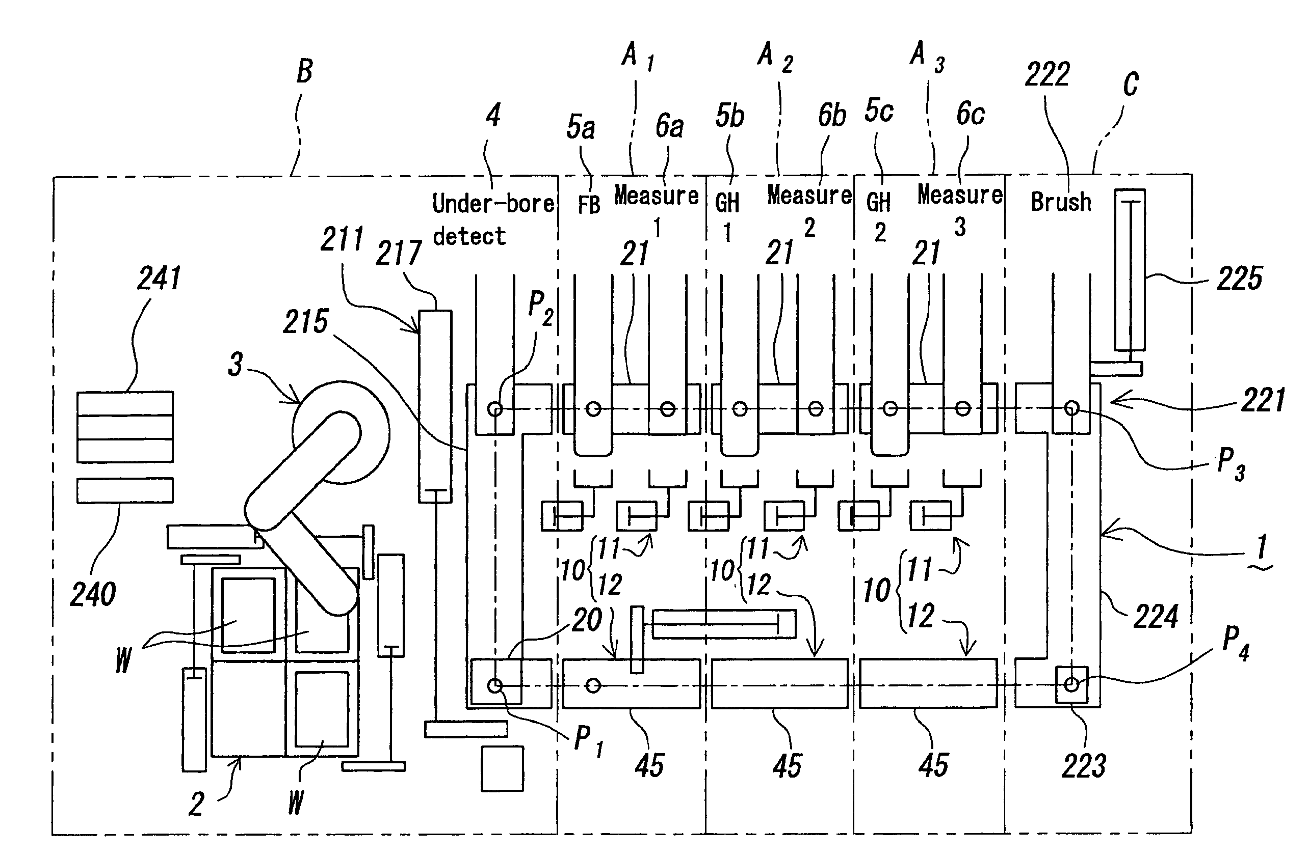
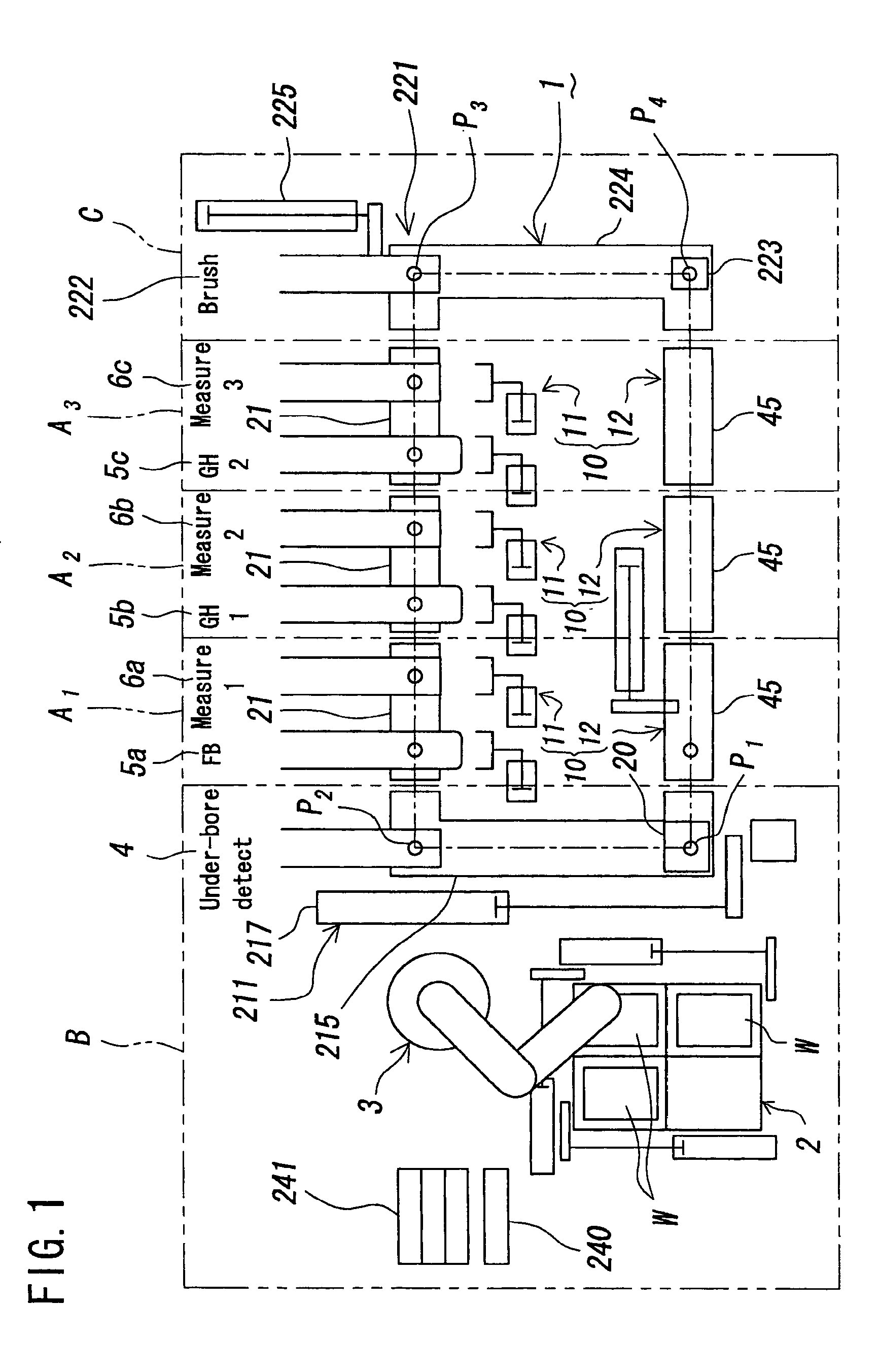
[0073]The automatic honing system of the present invention is shown in FIG. 1, and in the system, work W, W . . . are continuously carried at predetermined intervals along work carrying passage 1, and sequentially continuous honing is executed on the work WI W, . . . .

[0074]In the above automatic honing system, specifically, loading cell B and unloading cell C are arranged in series fashion at either side of a plurality (three units in the figure) of processing cells or machining cells A1, A2, A3 which are of unit structure.

[0075]The automatic honing system with these machining cells A1, A2, A3, B, C has a configuration including main components such as the work carrying passage ...


PUM

PropertyMeasurementUnit
outer diameteraaaaaaaaaa
unit structureaaaaaaaaaa
diameteraaaaaaaaaa

Abstract

A processing cell of automatic machining system configured in that it is easy to decide or change the number of steps and to design, and to reduce the installation cost. The control unit of the processing cell comprises an operation data storing means for storing every position necessary data for operation at each position of the processing cell installed in the machining section of the automatic machining system, and a position designating means for designating the after-installation position. The control unit reads necessary data for operation out of the operation data storing means in accordance with the position designated by the position designating means. Thus, the operation of each cell can be switched in accordance with the position, and the processing cells can be easily changed in position and adjusted in quantity.

Description

[0001]This application is a continuation application of patent application Ser. No. 10 / 642,169, filed on Aug. 18, 2003.BACKGROUND OF THE INVENTION[0002]1. Field of the Invention[0003]The present invention relates to processing cells of automatic machining system and an automatic honing system, and more particularly, for example, to automatic machining techniques such as automatic honing executed on sub-machined work sequentially carried at predetermined intervals along a work carrying passage for sequentially continuous machining by means of a boring machine and a honing machine disposed halfway in the work carrying passage.[0004]2. Description of the Related Art[0005]For example, honing is available as one of machining methods for accurately finishing work bore surfaces. In honing, a honing tool and work are placed in a state of relatively floating, then the honing tool is given rotational and reciprocal motion, and the work bore surfaces are accurately finished while expanding the...

Claims


Application Information

Patent Timeline
Patent Type & Authority Applications(United States)
IPC IPC(8): G06F17/00B23Q7/14B24B33/00B24B33/02B24B51/00
CPCB23Q7/1478B24B33/02B24B51/00Y10T408/08Y10T408/3809Y10T29/5136Y10T408/54Y10T408/05Y10T408/35Y10T29/5124B24B33/00
Inventor OOE, HIROYUKIFUJIMURA, TORUTSUJI, KAZUHIKOTOMITA, YASUO
Owner NISSIN MFG CO LTD
Why Eureka
Try Eureka