

Nail clipper
- Summary
- Abstract
- Description
- Claims
- Application Information
AI Technical Summary
Benefits of technology
Problems solved by technology
Method used
Image

Examples
Embodiment Construction
[0017]The nail clipper shown in FIG. 1 is conventional and comprises a pair of sprung blades 10, 12 riveted to one another at one end 14 and having accurately machined and aligned cutting edges 16 and 18 at their opposite ends. A pin 20 passing through a hole near the cutting edges 16 and 18 acts as a pivot for a lever arm 22 having a projection 24 which acts to squeeze the two cutting edges 16 and 18 together as the lever 22 is pivoted counter clockwise as viewed. A disadvantage of such a nail clipper, which the invention seeks to overcome, is that it cannot be used by a disabled person who has lost one arm to trim the nails of the single remaining hand.
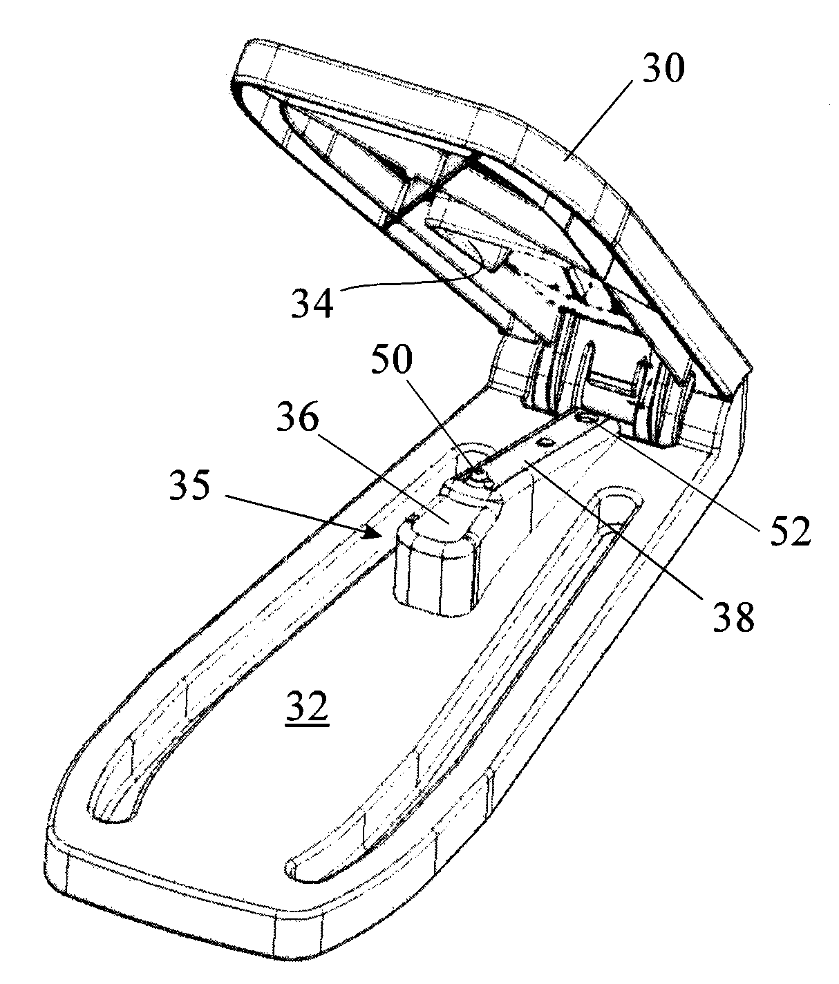
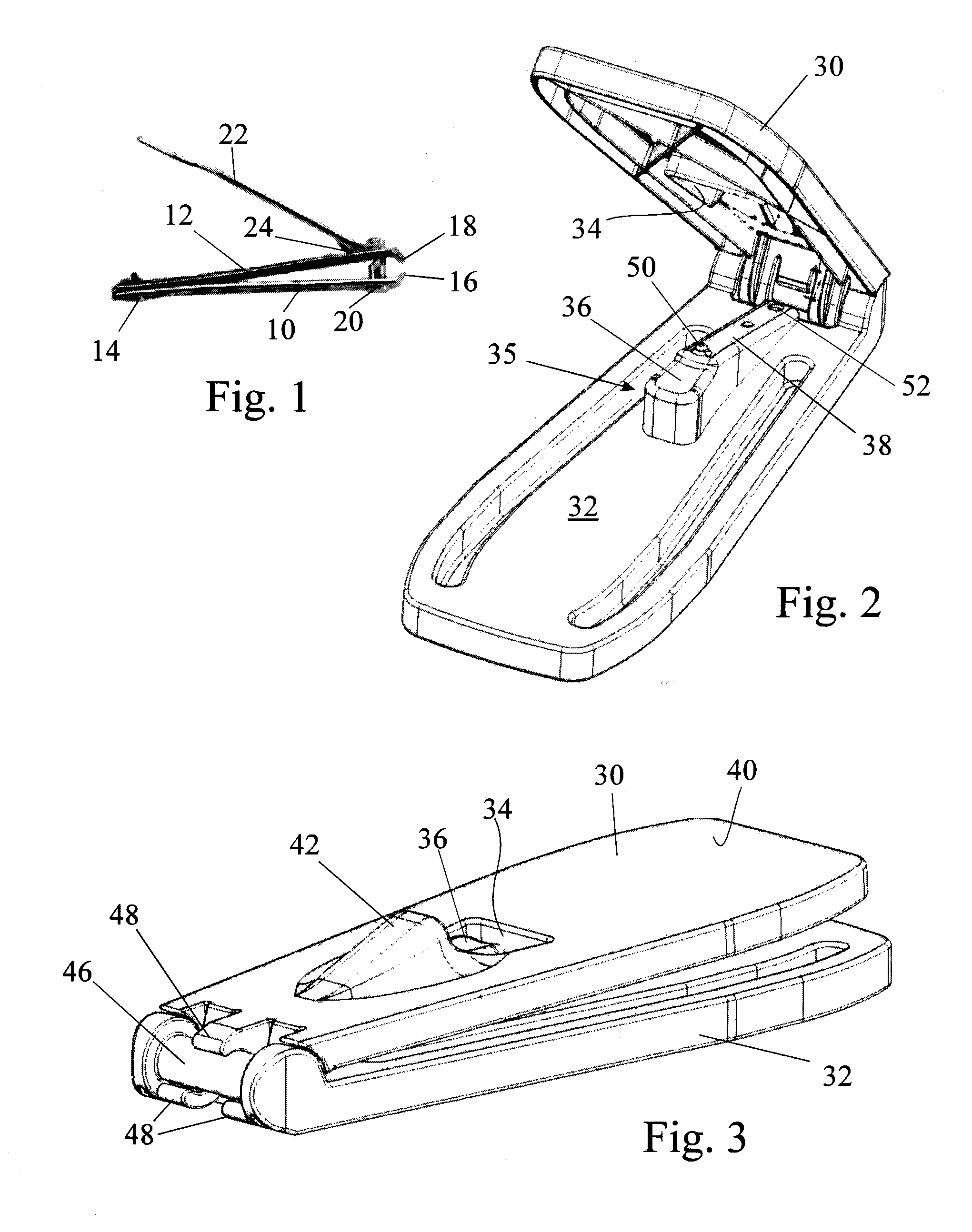
[0018]The nail clipper shown in FIGS. 2 and 3 is designed to make use of the cutting blades 10 and 12 only of the nail clipper shown in FIG. 1 after removal of the pin 20 and the lever arm 22. The parts of the nail clipper shown in FIGS. 2 and 3 act as a replacement for the lever arm 22 and make it easier for a disabled or infirm pe...
PUM
 Abstract
Description
Claims
Application Information