Fire barrier

a fire barrier and a technology for fire barriers, applied in fireproofing, furniture, lighting and heating apparatus, etc., can solve the problems of inability to properly orient intumescent sheets, easy joint expansion and contraction,

Active Publication Date: 2008-07-24
BALCO
View PDF12 Cites 165 Cited by
  • Summary
  • Abstract
  • Description
  • Claims
  • Application Information

AI Technical Summary

Benefits of technology

[0005]Embodiments of the present invention solve the above-described problems and provide a distinct advance in the art of fire barriers. More particularly, various embodiments of the invention provide a fire barrier including a plurality of intumescent sections which may be securely and properly positioned within a gap.

Problems solved by technology

Unfortunately, prior art fire barriers often fail to properly orient intumescent sheets within joints and are susceptible to joint expansion and contraction.

Method used


Image

  • Fire barrier
  • Fire barrier
  • Fire barrier

Examples


Embodiment Construction

[0016]The following detailed description of various embodiments of the invention references the accompanying drawings that illustrate specific embodiments in which the invention can be practiced. The embodiments are intended to describe aspects of the invention in sufficient detail to enable those skilled in the art to practice the invention. Other embodiments can be utilized and changes can be made without departing from the scope of the present invention. The following detailed description is, therefore, not to be taken in a limiting sense. The scope of the present invention is defined only by the appended claims, along with the full scope of equivalents to which such claims are entitled.

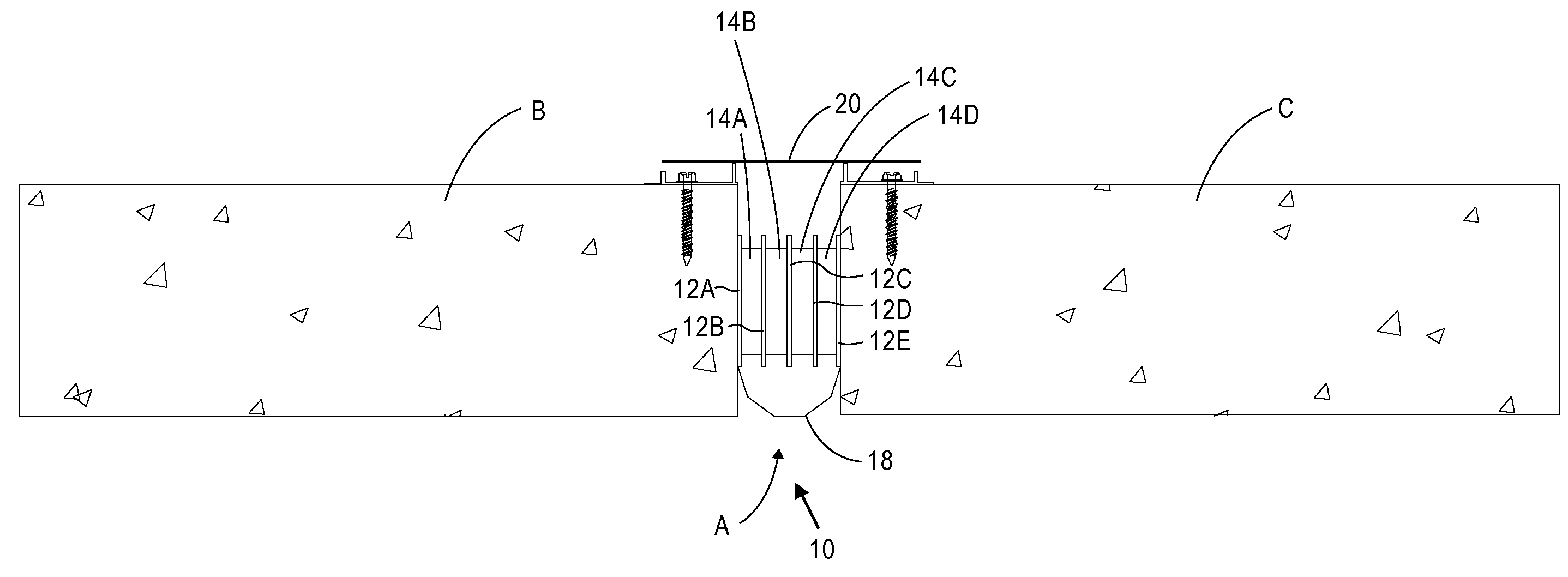
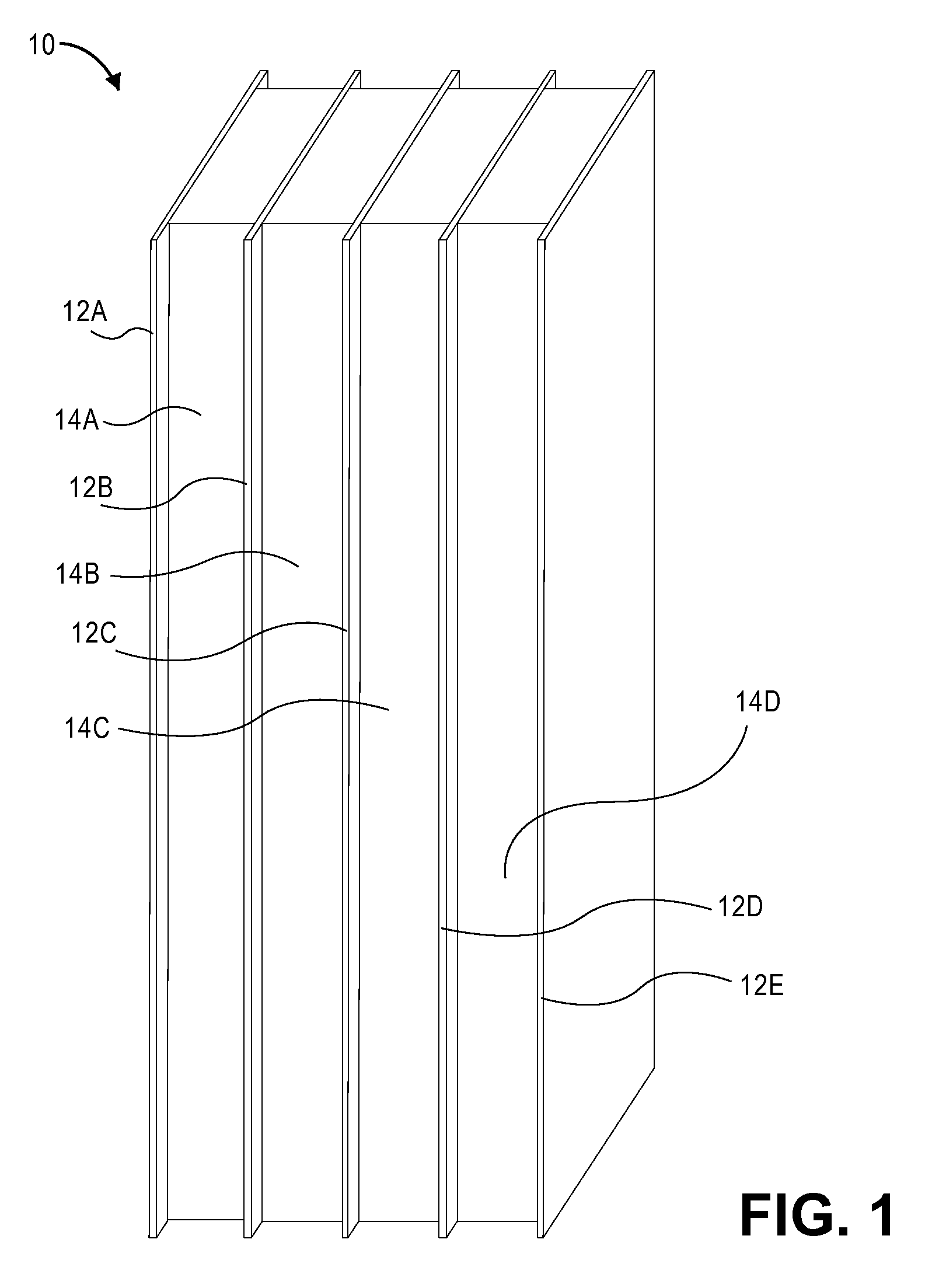
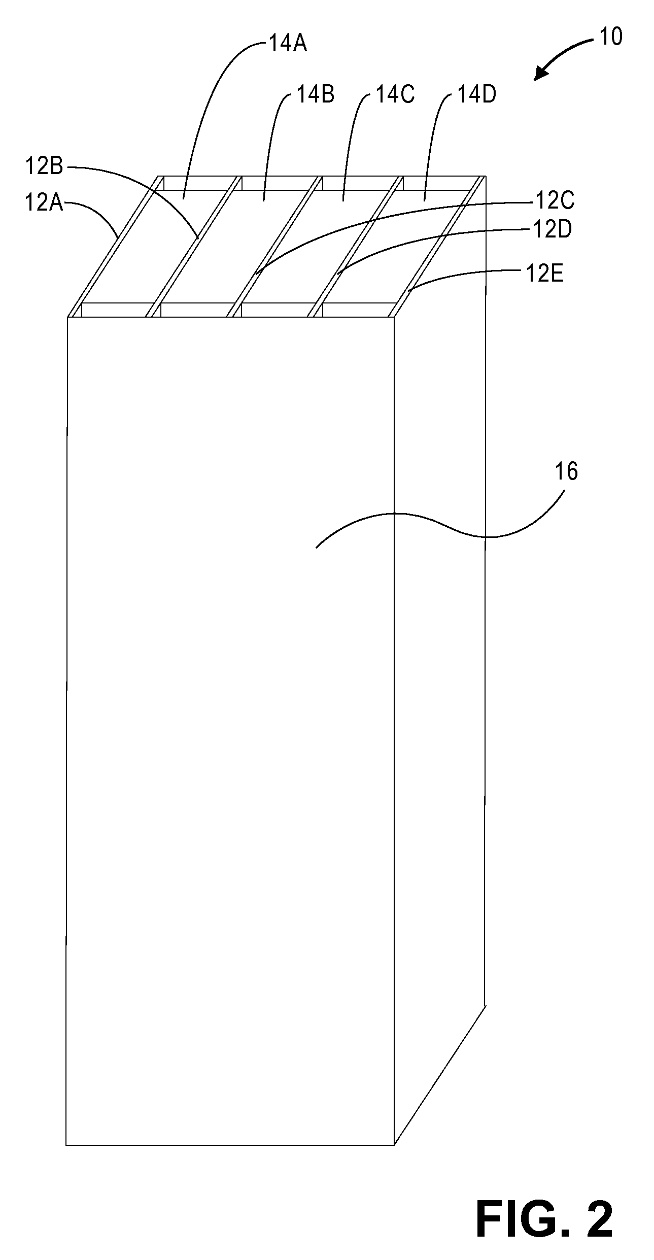
[0017]Referring to FIGS. 1-6, embodiments of the present invention provide a fire barrier 10 operable to be positioned within a gap A formed between two surfaces B, C. The barrier 10 may be installed within gaps between surfaces including roof, wall, floor, ceiling members, combinations thereof, o...


PUM


Abstract

A fire barrier operable to be placed within a gap formed between two surfaces. The fire barrier may generally include a first intumescent section, a first foam section coupled with the first intumescent section, and a second intumescent section coupled with the first foam section generally opposite the first intumescent section. In some embodiments, the fire barrier may include a plurality of intumescent sections and a plurality of foam sections with each foam section being positioned between at least two of the intumescent sections.

Description

BACKGROUND[0001]1. Field[0002]Embodiments of the present invention relate to fire barriers. More particularly, various embodiments of the invention provide a fire barrier including a plurality of intumescent sections.[0003]2. Description of the Related Art[0004]It is often desirable to position fire-resistive materials such as intumescent sheets within joints formed between roof, wall, floor, and ceiling members. Unfortunately, prior art fire barriers often fail to properly orient intumescent sheets within joints and are susceptible to joint expansion and contraction.SUMMARY[0005]Embodiments of the present invention solve the above-described problems and provide a distinct advance in the art of fire barriers. More particularly, various embodiments of the invention provide a fire barrier including a plurality of intumescent sections which may be securely and properly positioned within a gap.[0006]For example, various embodiments of the present invention provide a fire barrier that is...

Claims


Application Information

Patent Timeline
Patent Type & Authority Applications(United States)
IPC IPC(8): E04B1/94E04B1/62E04B1/74
CPCE04B1/948Y10S428/92E04B1/947E04B1/946C09K21/00
Inventor HILBURN, JOHNNIE DANIEL
Owner BALCO
Why Eureka
Try Eureka