
Universal Pliers

Inactive Publication Date: 2008-07-24
WU NA
View PDF12 Cites 9 Cited by
  • Summary
  • Abstract
  • Description
  • Claims
  • Application Information

AI Technical Summary

Benefits of technology

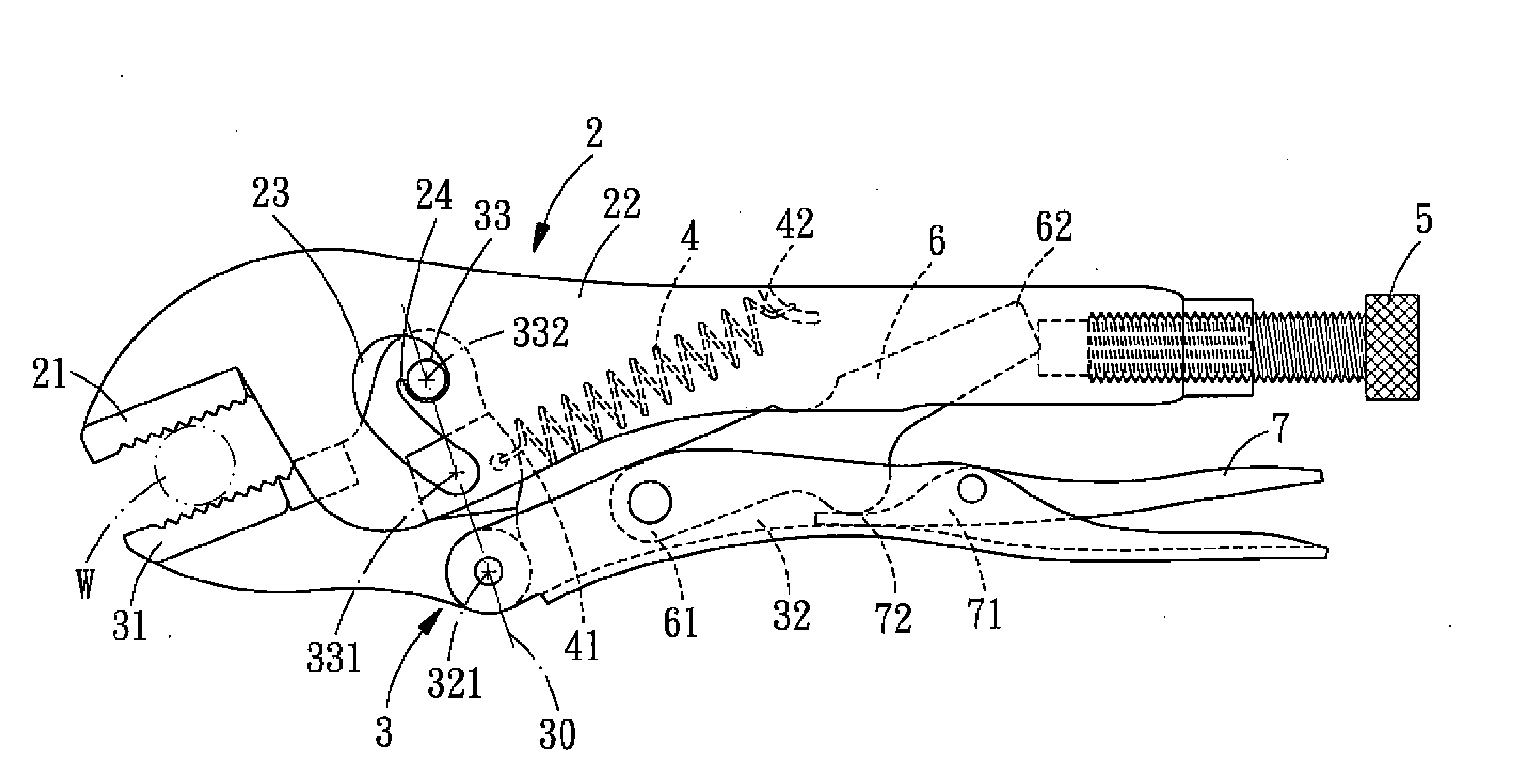
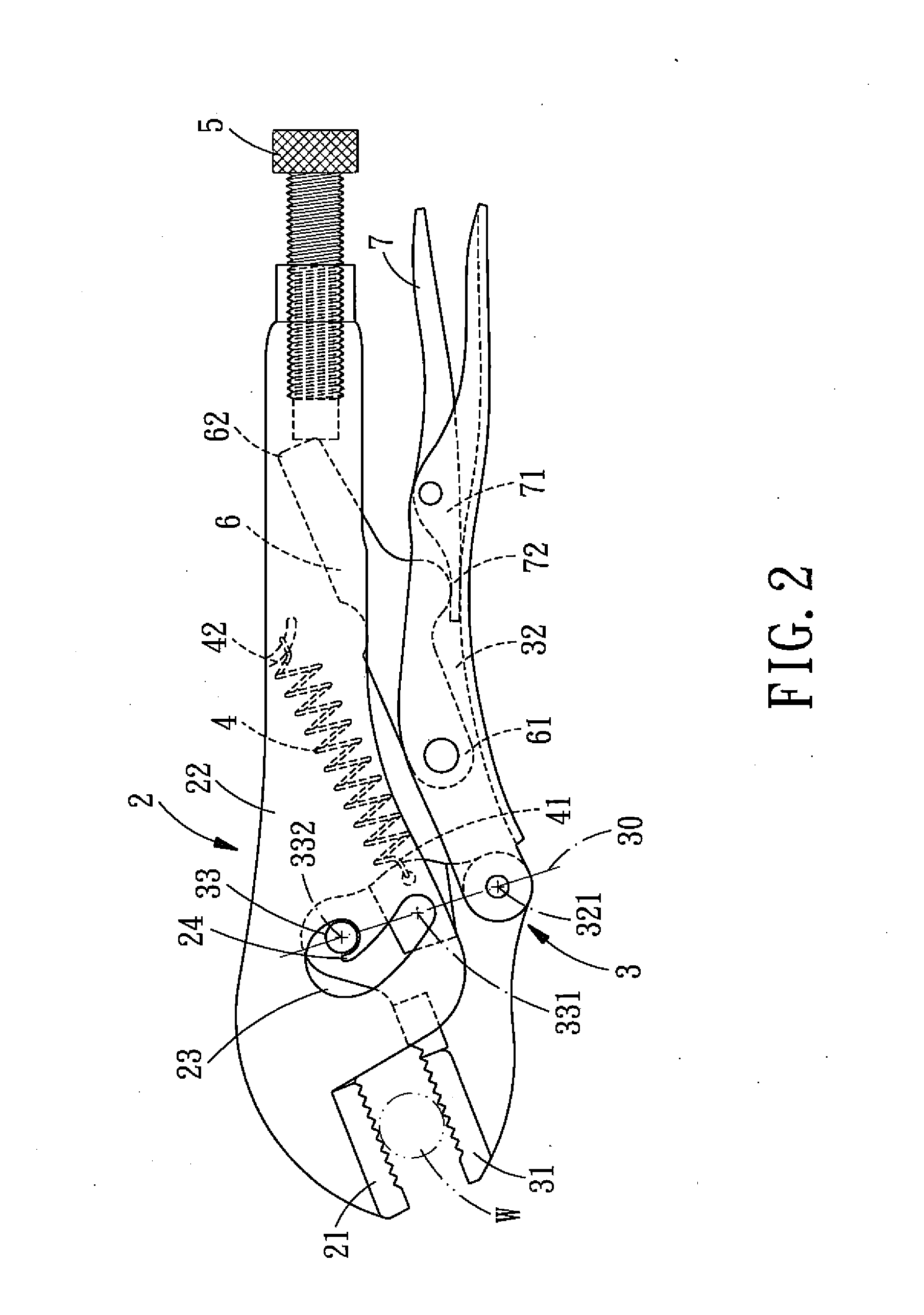
[0007]The primary objective of the present invention is to provide a pair of universal pliers. A pivot point where the second handle is pivotally coupled to the second jaw, an end point of the arc-shaped groove, and the other end point of the arc-shaped groove are arranged on the same straight line, so that no matter the pivot pin is positioned at either end point of the arc-shaped groove, it ensures that the first jaw is opened or closed horizontally with respect to the second jaw. Thereby, it is helpful to clamping a work piece in a surface-to-surface manner, thus ensuring a firm clamping operation against slippage.
[0009]The third objective of the present invention is to provide a pair of universal pliers, wherein, the pivot pin provided for pivotally coupling the first plier body to the second plier body is allowed to move in the arc-shaped groove. Since the arc-shaped groove is formed with a stopping portion, in addition, the pivot pin is under the tense operation of an extension spring, the pivot pin is confined by the stopping portion when it is positioned in a position. So that it is not likely to slip out of the position by a force when clamping a work piece, consequently, ensure a firm clamping of the work piece against any loose situation.

Problems solved by technology

Thus, several pairs of conventional universal pliers capable of being applied to some different size ranges must be prepared in order to clamp different sized work pieces, so it is quite inconvenient in use.
Afterwards, a pair of universal pliers capable of being applied to different size range work pieces was developed, but because the universal pliers can't clamp firm after being changed to different working sizes and it is likely to jump from a working size to another working size suddenly by an excessive force applied during the operating process.
So the effect of clamping a work piece is not good, and the practicality is not fine.

Method used


Image

  • Universal Pliers
  • Universal Pliers
  • Universal Pliers

Examples


Embodiment Construction

[0013]The present invention will be clearer from the following description when viewed together with the accompanying drawings, which show, for purpose of illustrations only, the preferred embodiment in accordance with the present invention.

[0014]A pair of universal pliers in accordance with the preferred embodiment of the present invention (please refer to FIGS. 2-3) comprises a first plier body 2, a second plier body 3, an extension spring 4, an adjusting rod 5, a linkage bar 6 and a turning rod 7.

[0015]The first plier body 2 includes a first jaw 21 integral with a hollow first handle 22, namely the first jaw 21 is connected with one end of hollow handle 22 after the first plier body 2 is formed. It is to be noted that, in each side of the hollow first handle 22 of the first plier body 2 is oppositely formed an arc-shaped groove 23, and each arc-shaped groove 23 is formed with a stopping portion 24.

[0016]The second plier body 3 includes a second jaw 31 and a hollow second handle 3...


PUM


Abstract

A pair of universal pliers comprises a first plier body, a second plier body, an extension spring, an adjusting rod, a linkage bar and a turning rod. A pivot point where the second handle is pivotally coupled to the second jaw, an end point of the arc-shaped groove, and the other end point of the arc-shaped groove are arranged on the same straight line, so that no matter the pivot pin is positioned at either end point of the arc-shaped groove, it ensures that the first jaw is opened or closed horizontally with respect to the second jaw. Consequently, it doesn't only have a wide application range, but also the tense operation of the extension spring is helpful to clamping a work piece in a surface-to-surface manner, thus ensuring a firm clamping operation against slippage.

Description

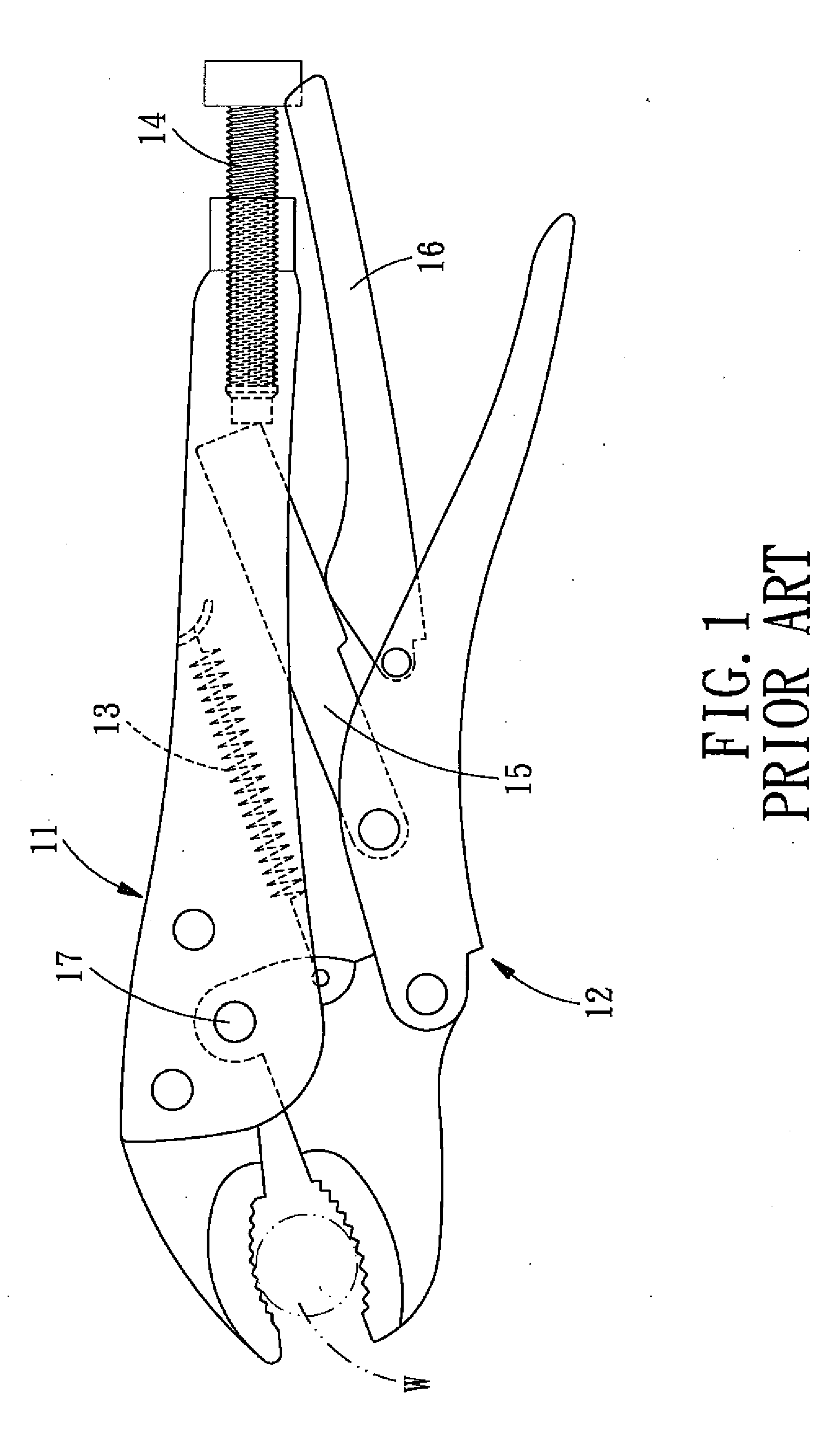
[0001]This application is a continuation of part of U.S. patent application Ser. No. 11 / 625,399. filed on Jan. 22, 2007, which claims the benefit of the earlier filing date.BACKGROUND OF THE INVENTION[0002]1. Field of the Invention[0003]The present invention relates to a pair of universal pliers and more particularly to an improved structure for a pair of universal pliers that is applied widely and can firm clamp a work piece.[0004]2. Description of the Prior Art[0005]A pair of conventional universal pliers (as shown in FIG. 1) comprises a first plier body 11, a second plier body 12, an extension spring 13, an adjusting rod 14, a linkage bar 15 and a turning rod 16. Since the first body 11 and the second body 12 are connected with each other through a pivot pin 17, the maximum open angle between the first plier body 11 and the second plier body 12 will be quite limited, and the size range of a work piece W capable of being clamped is quite confined, namely there is no problem in cla...

Claims


Application Information

Patent Timeline
IPC IPC(8): B25B7/00
CPCB25B7/123B25B7/10
Inventor WU, MING-CHIEH
Owner WU NA
Learn More