
Toner container, developer replenishing device, and image forming apparatus

a technology of toner container and developer, which is applied in the direction of electrographic process apparatus, instruments, optics, etc., can solve the problems of troublesome attachment and detachment of the container, difficulty in inserting fingers between two adjacent toner containers, and inability to facilitate the user to hold the container with ease. , to achieve the effect of holding the container easily and securely

Active Publication Date: 2008-07-24
KYOCERA DOCUMENT SOLUTIONS INC
View PDF11 Cites 46 Cited by
  • Summary
  • Abstract
  • Description
  • Claims
  • Application Information

AI Technical Summary

Benefits of technology

[0009]An object of the present invention is to provide a technology which can allow a user to hold a container easily and securely, thereby enabling the user to attach and detach the container to and from the image forming apparatus.

Problems solved by technology

However, if the user attempts to attach and detach the toner container while he / she is holding the container, the container is not always in a state of enabling the user to hold it with ease.
In this regard, there are often such cases that the user cannot stably hold the container, which causes a troublesome in attachment and detachment of the container.
Also, if the image forming apparatus, for example, is for the use of multi-color print in which a plurality of toner containers containing different colors of toner are installed side by side into the apparatus main body, there have been such problems that it is difficult to insert fingers between two adjacent toner containers and thus to hold the container easily and securely.

Method used


Image

  • Toner container, developer replenishing device, and image forming apparatus
  • Toner container, developer replenishing device, and image forming apparatus
  • Toner container, developer replenishing device, and image forming apparatus

Examples


first embodiment

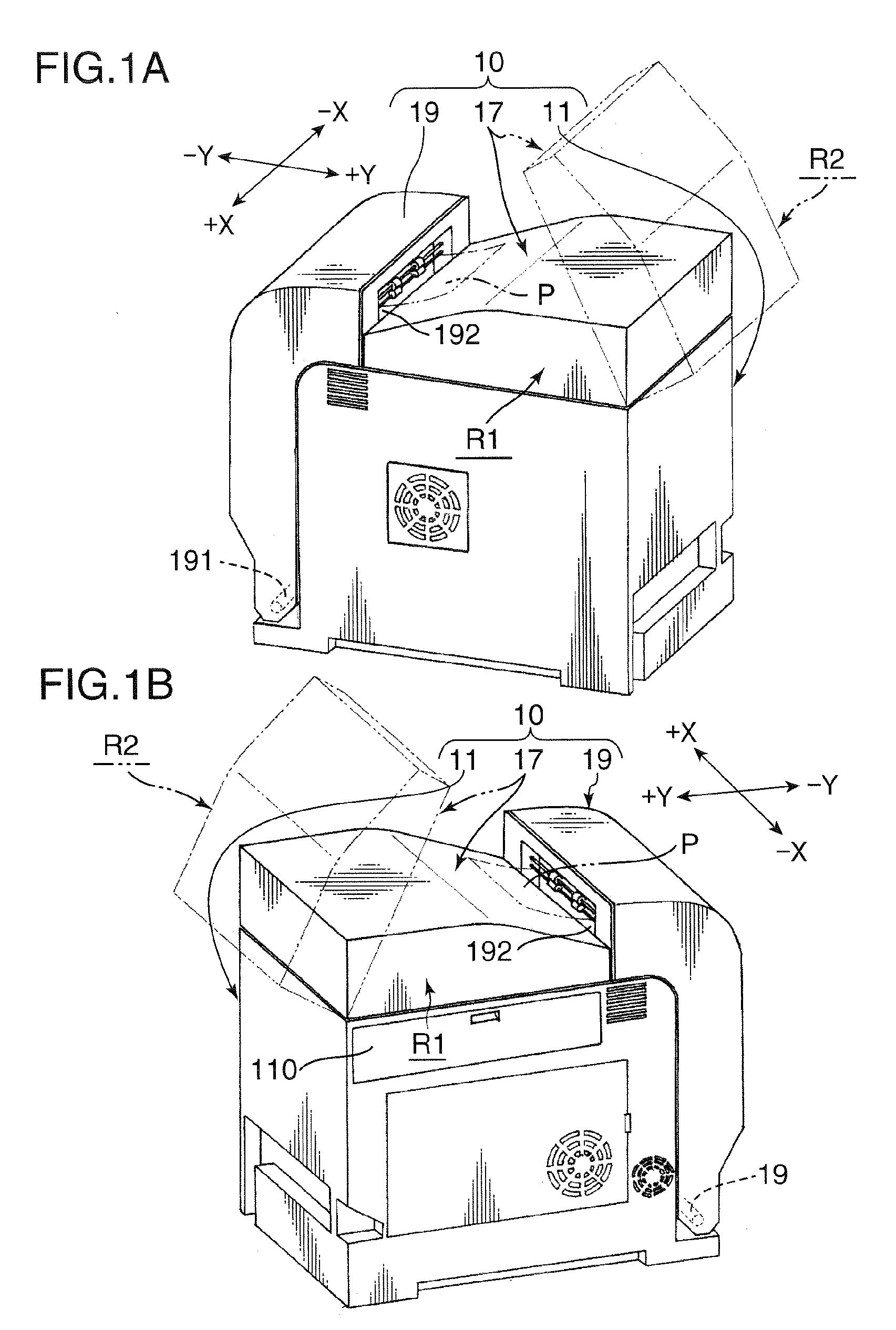
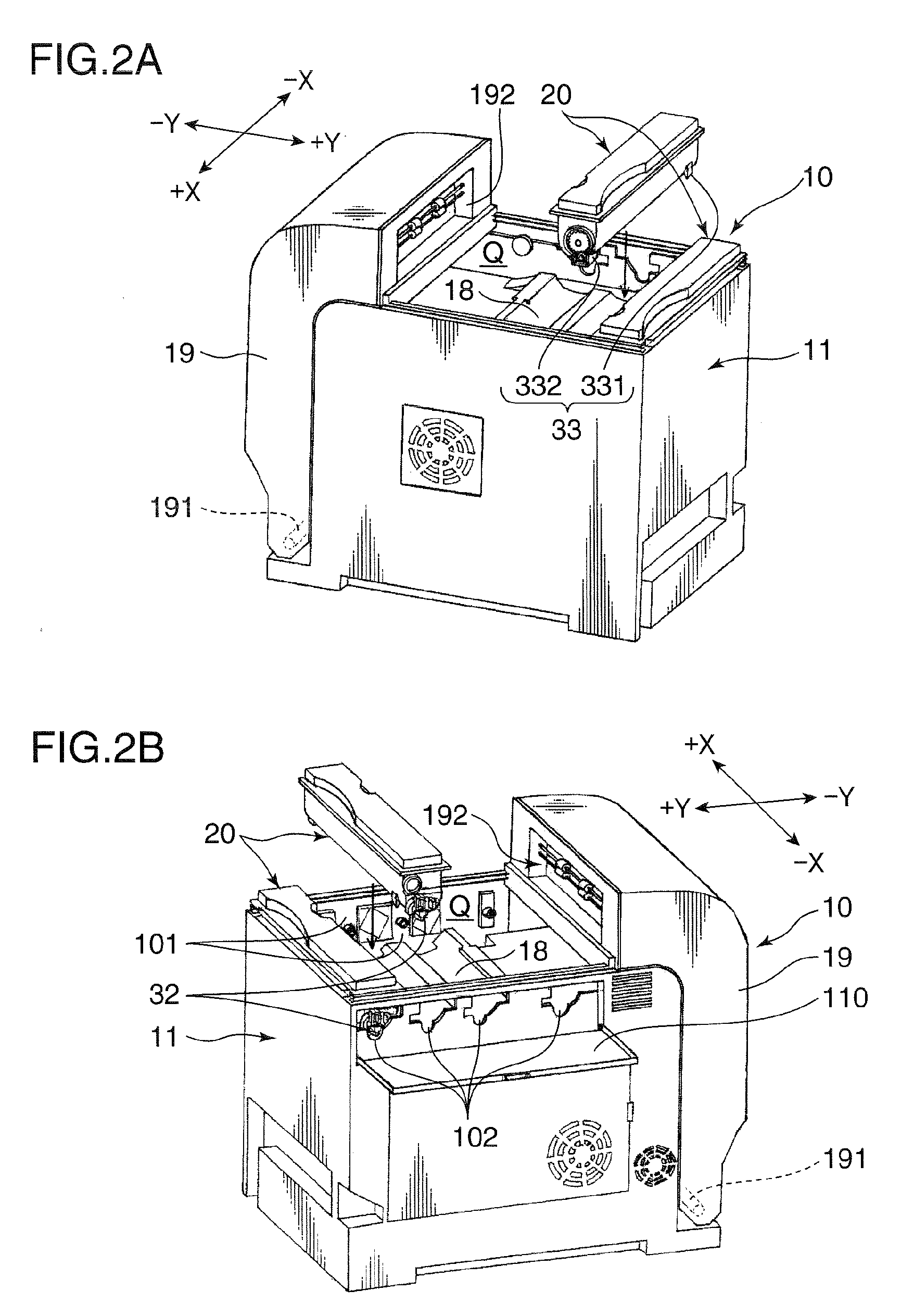
[0037]An image forming apparatus to which a toner container 20 according to a first embodiment is applied will be briefly described with reference to FIGS. 1, 2, and 3, exemplifying a printer 10.

[0038]FIGS. 1A through 2B are external perspective views illustrating the printer 10. FIGS. 1A and 1B illustrate a paper output tray 17 installed in an apparatus main body 11; and FIGS. 2A and 2B illustrate the paper output tray 17 removed from the apparatus main body 11. FIGS. 1A through 2B are external perspective views illustrating the printer to which the toner container is provided.

[0039]FIGS. 1A and 2A are perspective views when the printer is viewed from a right rear direction; and FIGS. 1B and 2B are perspective views when the printer is viewed from a left rear direction. FIG. 3 is a cross sectional view of an internal structure of the apparatus main body 11 viewed from a left side. In FIGS. 1 through 3, the X-X direction is referred to as a widthwise direction and the Y-Y direction ...

second embodiment

[0199]Now, a toner container 20A according to a second embodiment will be described. FIGS. 21A and 21B are perspective views illustrating a toner container 20A. FIG. 21A illustrates a container 30′ with a covering cap 70′ removed; and FIG. 21B illustrates the container 30′ with the covering cap 70′ installed therein, respectively. Directions indicated by X and Y in FIGS. 21A and 21B are identical to those indicated in FIG. 5 (X represents the widthwise direction (−X: leftward, +X: rightward) and Y represents the forward and backward direction (−Y: forward, +Y: backward)).

[0200]As shown in FIG. 21A, the present embodiment differs from the former embodiment in that the toner container 20A is given a vertical dimension of the rear side portion 313 of a container main body 31′ shorter than a vertical dimension of the front side portion 312 of the container main body 31′, whereby a top surface of the container main body 31′ inclines downward in a backward direction in a side view (viewed...


PUM


Abstract

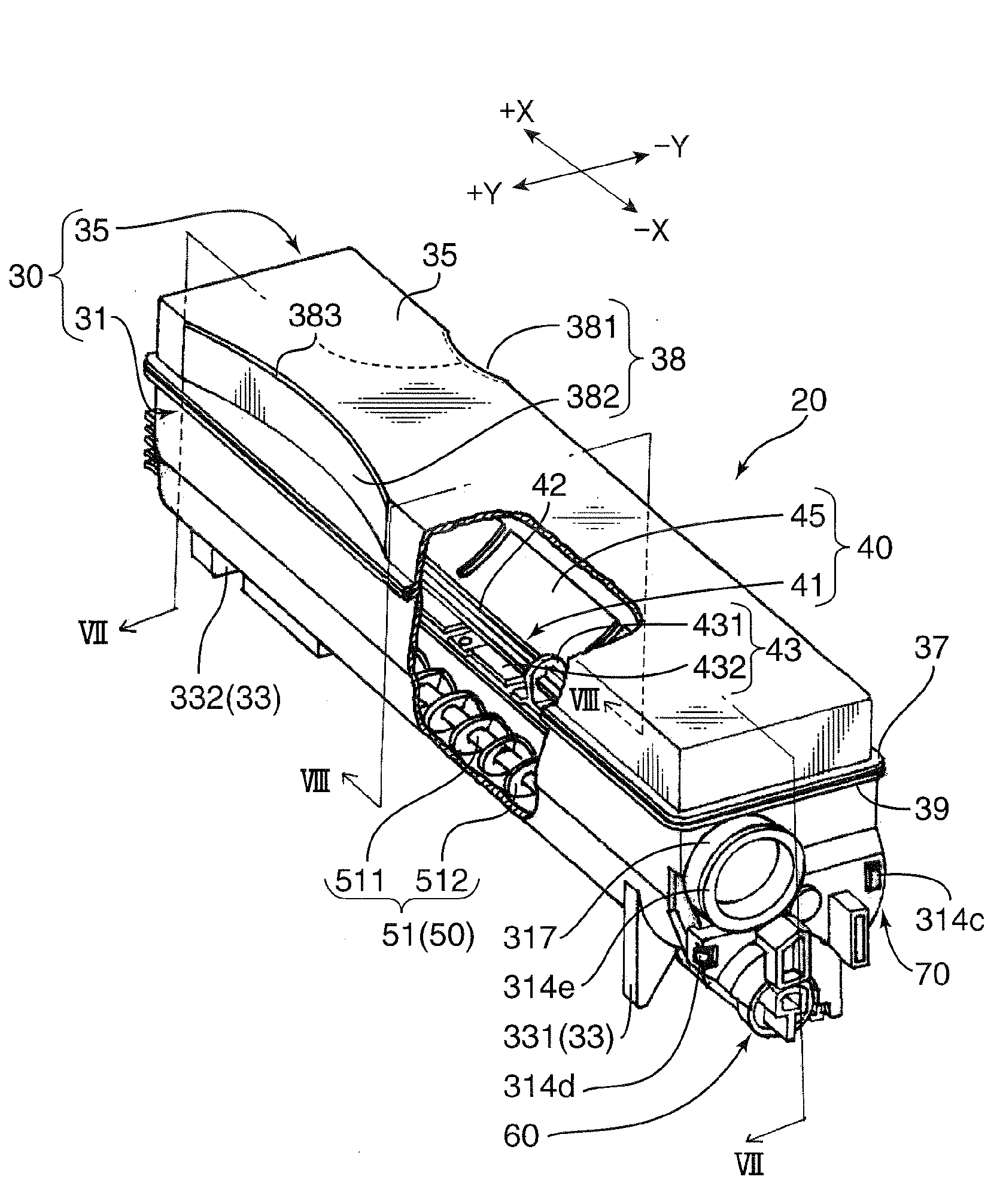
A toner container adapted for containing toner includes a first side wall and a second side wall opposed to each other. The toner container longitudinally extends between the first side wall and the second side wall and includes a handle to be held when the container is attached to or detached from the apparatus main body and a retaining portion provided on the first side wall to be engaged with a portion of the apparatus main body when the container is installed in the apparatus main body. The handle is provided at a position shifted to the second side wall from a center of the container in the longitudinal direction.

Description

BACKGROUND OF THE INVENTION[0001]1. Field of the Invention[0002]The present invention relates to a toner container and a developer replenishing device which is detachably installed to an image forming apparatus, such as a copying machine, a printer, a facsimile machine, and the like with toner, in order to replenish a developing device provided in the image forming apparatus, and an image forming apparatus to which such toner container or developer replenishing device is installed.[0003]2. Description of the Related Art[0004]A toner container disclosed in Japanese Unexamined Patent Publication (Kokai) No. 2003-280344 is known as prior art. The toner container includes a box-like container to be charged with toner and a toner replenishing device provided at a bottom of the container in order to discharge toner to replenish a developing device with the toner.[0005]Such a toner container is attached to or detached from an apparatus main body with an end (for example, top end corner) of...

Claims


Application Information

Patent Timeline
IPC IPC(8): G03G15/08
CPCG03G15/087G03G15/0875
Inventor ETO, DAISUKENISHIMURA, TOSHINORIIKEBATA, YOSHIAKI
Owner KYOCERA DOCUMENT SOLUTIONS INC
Learn More