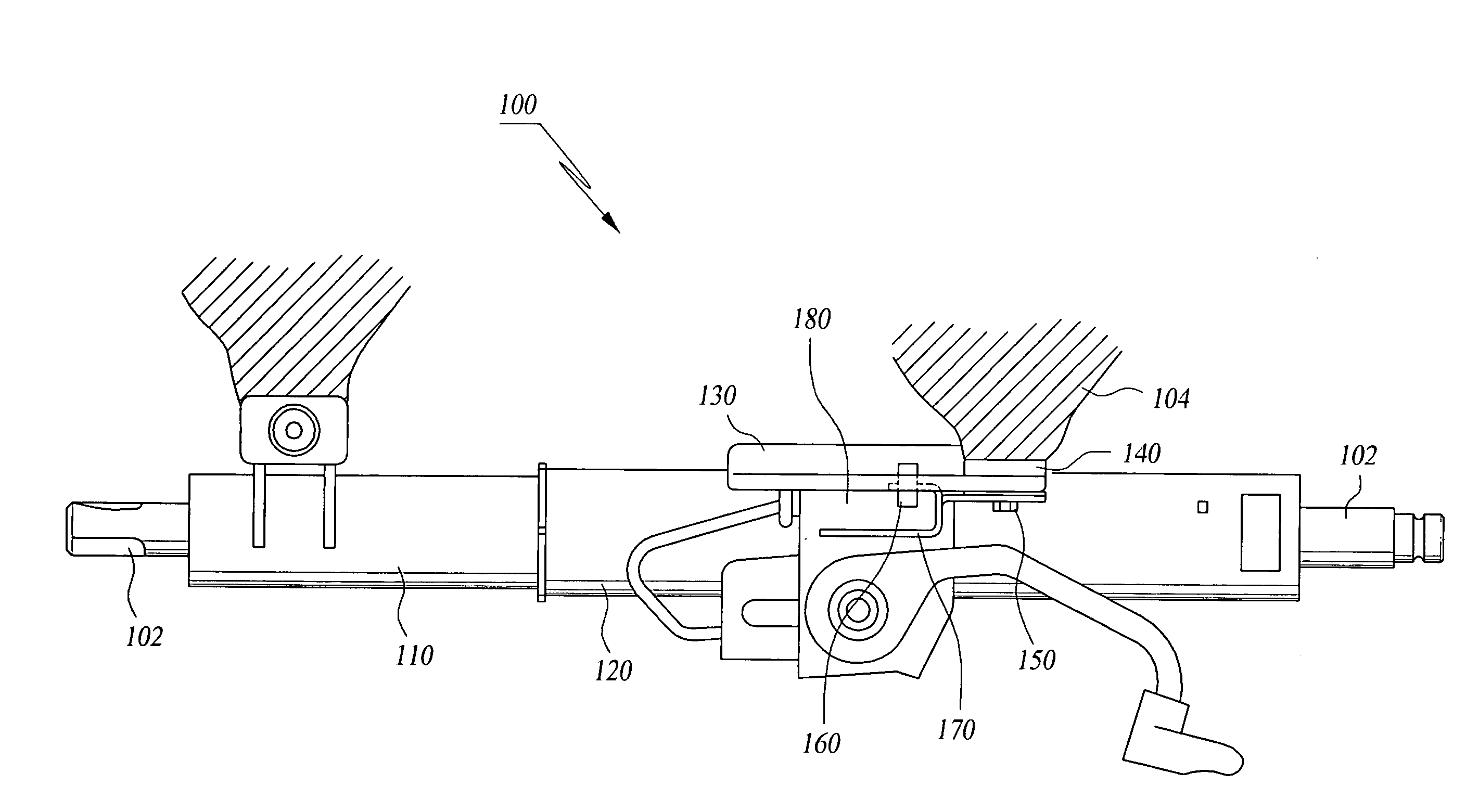
Impact absorption steering apparatus
- Summary
- Abstract
- Description
- Claims
- Application Information
AI Technical Summary
Benefits of technology
Problems solved by technology
Method used
Image
Examples
first embodiment
[0045]The first protuberance 260 according to the present invention is formed in such a manner that a part having a uniform width and a predetermined depth is continuously formed, and then the width thereof decreases. Also, it is possible that the first protuberance 260 is formed in such a manner that width thereof decreases from one side to the other side without a part continuously formed while having a uniform width and a predetermined depth.
[0046]Herein, the part having the uniform width is necessarily bigger in comparison with the width of the first groove 270 so as to be forcibly engaged with the first groove 270.
[0047]In a case where the first protuberance 260 is formed as described above, when the steering column collapses, load due to collision is absorbed by friction generated between the first groove 270 and the first protuberance 260 while the part having a uniform width moves along the first groove 270. After this, when the first groove 270 escapes from the part having ...
third embodiment
[0050]According to the present invention, the second groove 320 can be formed at both ends of the first plate bracket 210. The second groove 320 has a width smaller than the width of the first plate bracket 210 as shown in FIG. 3b.
[0051]Herein, it is preferable that the shape of the protuberance engaged with the second groove 320 is the same as the shape of the second protuberance 310 as shown in FIG. 3c.
[0052]Impact is absorbed by an operation between the second groove 320 and the second protuberance 310 in such a manner as described below. The second protuberance 310 is forcibly engaged with the second groove 320 during normal time, but when impact is exerted on the steering column, the second protuberance 310 is disengaged from the second groove 320 so that impact is absorbed.
fourth embodiment
[0053]FIG. 4a is a sectional view of a structure where a mounting bracket and a plate bracket according to the present invention are assembled with each other. As shown in FIG. 4a, each third groove 440 is formed at a second mounting bracket 410, and each third protuberance 430 is formed at the second plate bracket 420 (the second mounting bracket 410 and the second plate bracket 420 have the same structure except for the third groove 440 and the third protuberance 430 in comparison with the first mounting bracket 220 and the first plate bracket 210).
[0054]FIG. 4b is a perspective view of the third protuberance formed at the plate bracket according to the fourth and fifth embodiments of the present invention, FIG. 4c is a perspective view of the third groove formed at an inner surface of a mounting bracket according to the fourth embodiment of the present invention, and FIG. 4d is a perspective view illustrating a fourth groove formed at an inner surface of a mounting bracket accord...
PUM
 Abstract
Description
Claims
Application Information
 - R&D Engineer
- R&D Manager
- IP Professional
- Industry Leading Data Capabilities
- Powerful AI technology
- Patent DNA Extraction
Browse by: Latest US Patents, China's latest patents, Technical Efficacy Thesaurus, Application Domain, Technology Topic.
© 2024 PatSnap. All rights reserved.Legal|Privacy policy|Modern Slavery Act Transparency Statement|Sitemap


