Half-wave rectification circuit with a low-pass filter for LED light strings

a technology of led light strings and rectification circuits, which is applied in the direction of discharge tube/lamp details, discharge tube incandescent screens, light and heating apparatus, etc., can solve the problem that the use of ac to dc converters with each led light string becomes substantially more expensiv

Active Publication Date: 2008-09-18
SANTAS BEST
View PDF9 Cites 37 Cited by
  • Summary
  • Abstract
  • Description
  • Claims
  • Application Information

AI Technical Summary

Benefits of technology

[0004]An embodiment of the present invention may therefore comprise an LED string circuit comprising: a plug that is adapted to fit in a standard household electrical socket; a half-wave rectification and low-pass filter circuit disposed in the plug comprising: a resistor having a resistance (R) that is connected to a first lead of an alternating current power source having a frequency (ƒo); a diode connected in series with the resistor; a capacitor connected between an output node of the diode and a second lead of the alternating current power source; an LED string, having a resistance (RLED) that is connected to the output node of the diode and the second lead of the alternating current power source, the LED string having an effective resistance (RLED); the capacitor having a capacitance (C) selected in accordance with:
[0005]An embodiment of the present invention may therefore further comprise a method of generating a substantially constant voltage for an LED string from an alternating current power source comprising: connecting a resistor having a resistance (R) to a first lead of the alternating current power source; connecting a diode in series with the resistor; connecting a capacitor having a capacitance (C) between an output node of the diode and a second lead of the alternating current power source; connecting the LED string between the output node of the diode and the second lead of the power source, the LED string having an effective resistance (RLED); selecting the value of the capacitance of the capacitor in accordance with:

Problems solved by technology

The use of AC to DC converters with each LED light string becomes substantially more expensive.

Method used


Image

  • Half-wave rectification circuit with a low-pass filter for LED light strings
  • Half-wave rectification circuit with a low-pass filter for LED light strings
  • Half-wave rectification circuit with a low-pass filter for LED light strings

Examples


Embodiment Construction

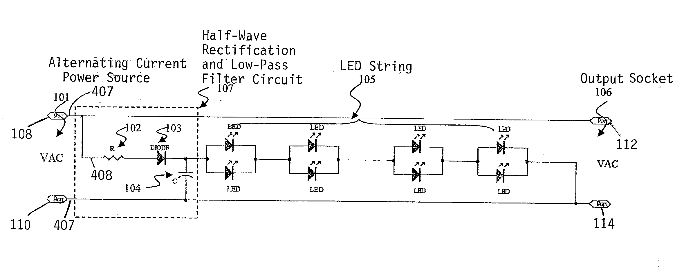
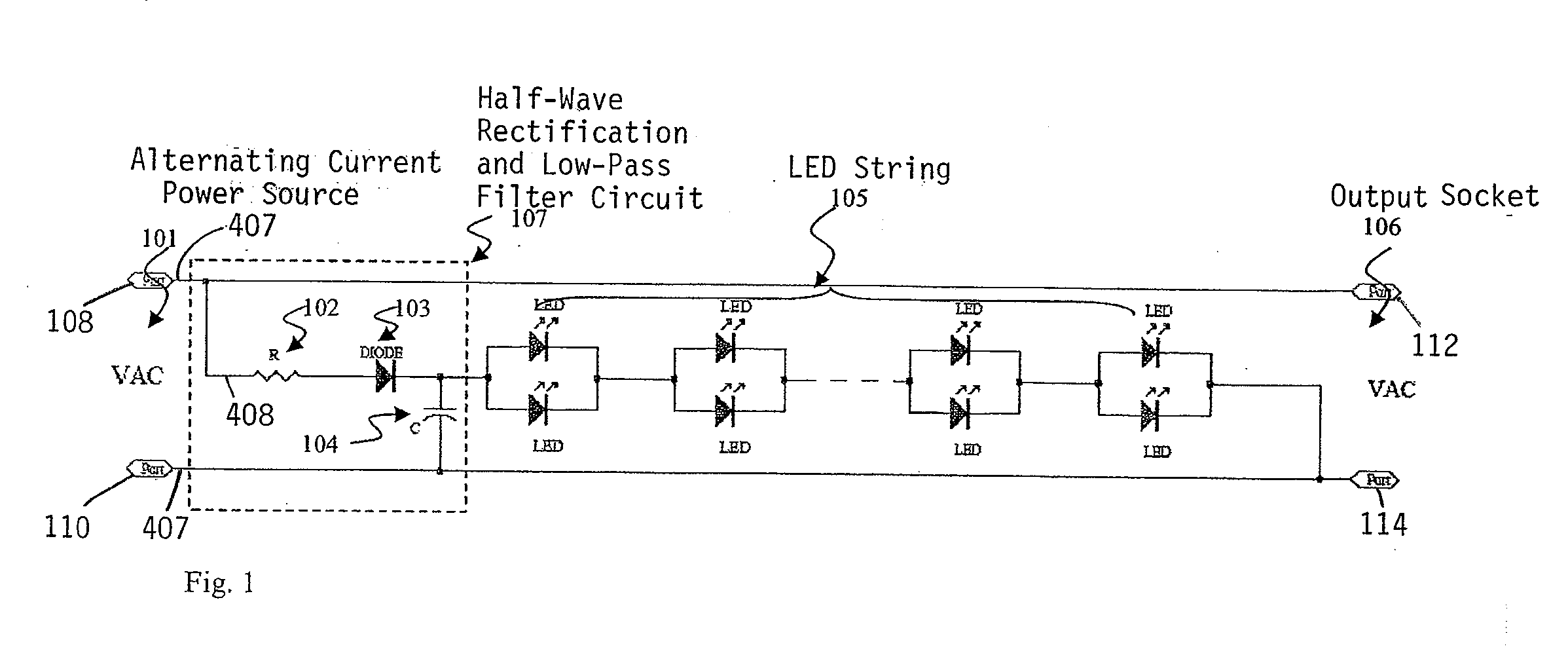
[0013]FIG. 1 is a circuit diagram of an LED string circuit that includes a half-wave rectification / low-pass filter circuit 107. As shown in FIG. 1, the half-wave rectifier / low-pass filter circuit 107 is an inexpensive circuit for providing a DC signal for LED string 105 that eliminates flicker and extends the lifetime of the LEDs 105. The half-wave rectifier / low-pass filter 107 provides a nearly constant DC voltage to the LED string 105 and utilizes low cost components, including a resistor 102, a diode 103 and a capacitor 104. The half-wave rectifier / low-pass filter 107 eliminates the cost of an AC to DC converter that is normally used in light strings to provide bright, non-glittering light sources. As shown in FIG. 1, an alternating current power source 101, such as a 117 volt rms household power source, is applied to input ports 108, 110. The half-wave rectification / low-pass filter circuit 107 is connected between the input ports 108, 110, the LED string 105 and output ports 112...


PUM


Abstract

Disclosed is a low cost LED string circuit design that uses an inexpensive half-wave rectification and low-pass filter circuit that is designed to produce minimal flicker in the LED string that is connected to the circuit. The components of the half-wave rectification and low-pass filter circuit are selected in accordance with design principles that prevent glittering and flickering of the LED string. The circuit components of the half-wave rectification and low-pass filter circuit can be embedded in an outlet plug or as a separate independent unit between an AC power plug and the LED string.

Description

CROSS-REFERENCE TO RELATED APPLICATION[0001]This application is a continuation-in-part of U.S. patent application Ser. No. 11 / 716,788, entitled “A Half-Wave Rectification Circuit With a Low-Pass Filter for LED Light Strings,” by Jing Jing Yu, filed Mar. 12, 2007. The entire contents of the above mentioned application is hereby specifically incorporated herein by reference for all it discloses and teaches.BACKGROUND OF THE INVENTION[0002]Light emitting diode (LED) strings have been used as decorative lighting and have become an important part of daily life. The properties of LEDs, such as low operating voltage and power, small size, long lifetime and extended stability, make them desirable as lighting sources. Moreover, LEDs do not generate a substantial amount of heat and are safe for daily operation.[0003]In conventional LED strings, LEDs are connected either directly to a standard household alternative current power source or through an AC to DC converter. Directly connecting an L...

Claims


Application Information

Patent Timeline
Patent Type & Authority Applications(United States)
IPC IPC(8): H05B33/02F21K7/00F21K99/00
CPCH05B33/0809H05B33/0803H05B45/00
Inventor YU, JING JING
Owner SANTAS BEST
Why Eureka
Try Eureka