Wastewater screening device

a screening device and wastewater technology, applied in gravity filters, sedimentation settling tanks, artificial water canals, etc., can solve the problems of tilting, operating problems, and devices typically do not have cross struts for support, so as to reduce the amount of material, reduce the effect of labor intensity

Active Publication Date: 2009-11-05
STEINHARDT
View PDF10 Cites 8 Cited by
  • Summary
  • Abstract
  • Description
  • Claims
  • Application Information

AI Technical Summary

Benefits of technology

[0015]One object of the present invention is to provide a screening device of the general type described above, which is configured in such a way that the screening rods can absorb relatively large forces, is economical to manufacture in terms of less material, and ensures that the wastewater flow through the gaps formed between adjacent rods has a substantially constant resistance over the length of the rods.

Problems solved by technology

These devices typically do not have any cross struts for support.
Fiberization and compacting therefore occurs, which lead to operating problems.
The pre-stressed rods are not entirely rigid (i.e., they can bend apart laterally owing to the water pressure and the prevailing speed, owing to the water turbulence, or else owing to the water pressure), so that they can oscillate or deflect, such that there is a risk that together with water constituents, small stones will also get lodged between the rods, causing tilting to occur when the wiping elements move through the rods, and attempt to realign the same.
If the stones do not become loose, because they have already wedged themselves too far in owing to the water pressure and the screening rods which are bending apart, this causes the system to fail.
Fiberization and compacting occur, which lead to operating problems.
However, the capital expenditure, statics, performance and operating costs are disadvantageous.
Furthermore, when heavy rain occurs, the screen floods from rainwater entering through the upper or clean water side of the screen, in which case water constituents or debris become deposited on the rear or clean water side of the screen and cause blockage.
The same type of blockage also occurs if stones or other items pass from the entry area onto the upper surfaces of the screening rods.
Furthermore, in devices having screening rods arranged lying flat, but which extend upwardly at the welding point, dirt collection spaces are created whose dimensions are significantly too small for large overflow quantities with a large dirt load and a large amount of screenings.
Relatively large dimensioned spaces are not possible, since the screenings will flow through the same.

Method used


Image

  • Wastewater screening device
  • Wastewater screening device
  • Wastewater screening device

Examples


Embodiment Construction

[0086]For purposes of description herein, the terms “upper”, “lower”, “right”, “left”, “rear”, “front”, “vertical”, “horizontal” and derivatives thereof shall relate to the invention as oriented in FIGS. 1 and 4. However, it is to be understood that the invention may assume various alternative orientations and step sequences, except where expressly specified to the contrary. It is also to be understood that the specific devices and processes illustrated in the attached drawings, and described in the following specification, are simply exemplary embodiments of the inventive concepts defined in the appended claims. Hence, specific dimensions and other physical characteristics relating to the embodiments disclosed herein are not to be considered as limiting, unless the claims expressly state otherwise.

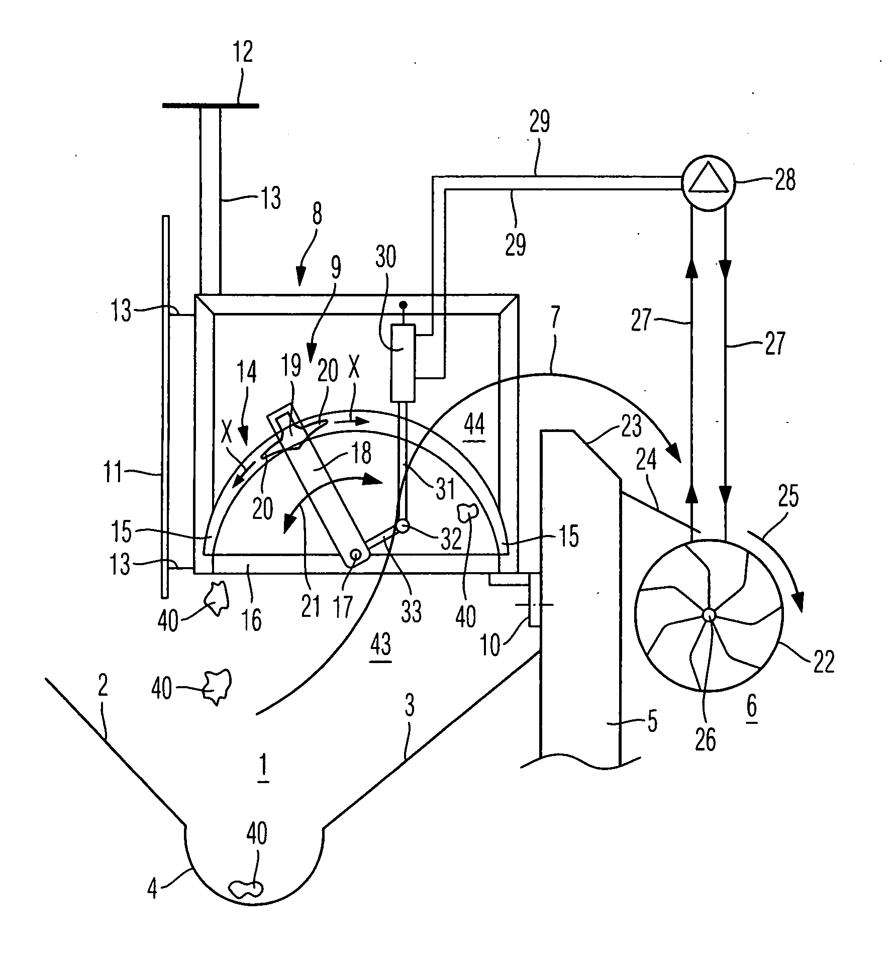
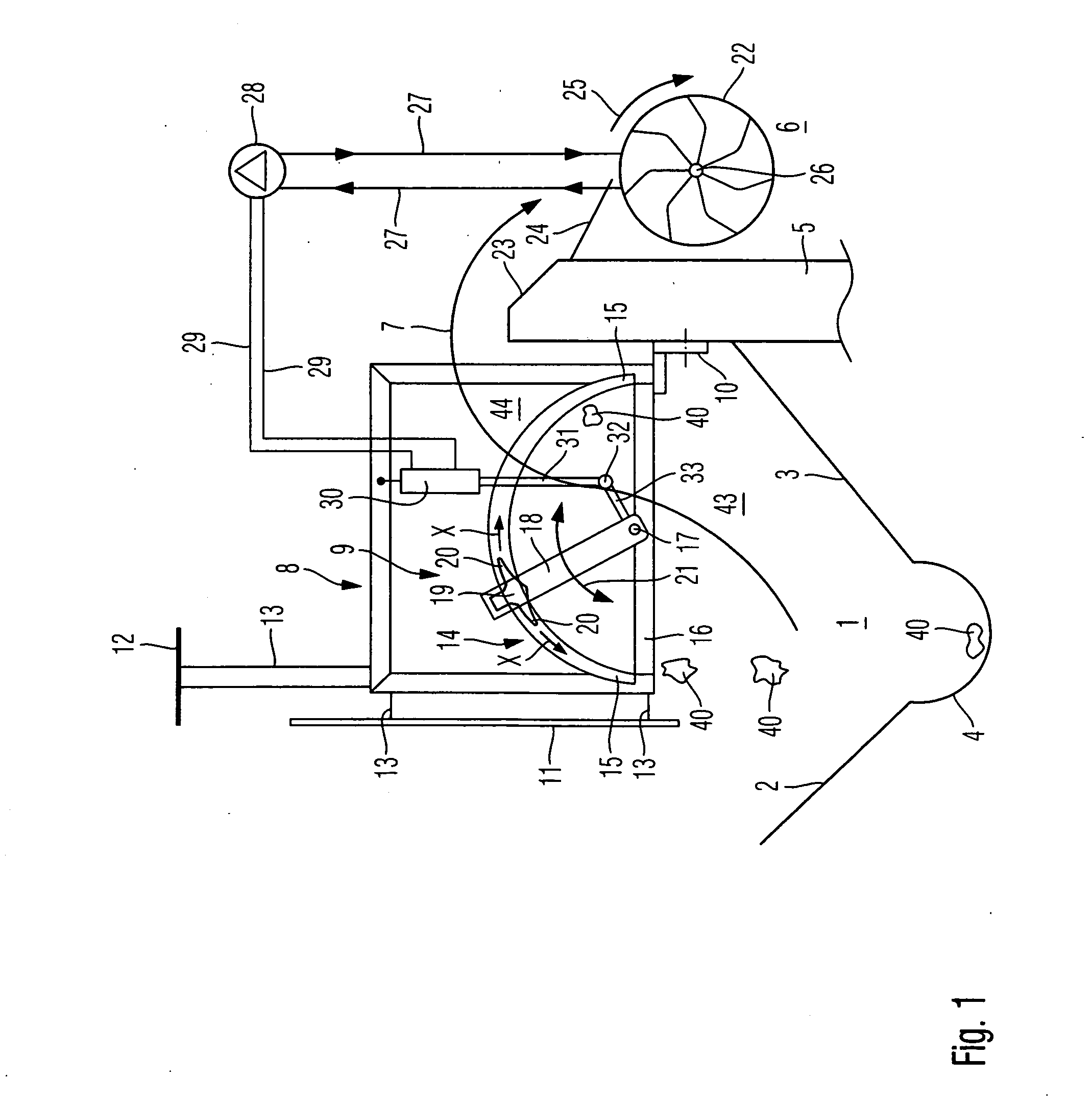
[0087]FIG. 1 illustrates a wastewater channel 1 with inclined floor sections 2 and 3 which extend toward one another, and a dry weather gully 4 which connects the two floor sections 2 and...


PUM

PropertyMeasurementUnit
distanceaaaaaaaaaa
distanceaaaaaaaaaa
distanceaaaaaaaaaa

Abstract

A screening device for wastewater overflow weirs and the like includes a perforate screening member through which wastewater flows from a bottom to top sides thereof, with a frame and a plurality of screening rods arranged in a laterally spaced apart, mutually parallel relationship. The opposite ends of the screening rods are fixedly connected with the frame to capture solids in the wastewater. The screening rods are each configured with narrow portions at the opposite ends.

Description

CLAIM OF PRIORITY[0001]Applicant hereby claims the priority benefits under the provisions of 35 U.S.C. § 119, basing said claim of priority on German Patent Application Serial No. 10 2008 022 167.8, filed May 5, 2008 and related European Patent Application Serial No. 08075897.2, filed Nov. 21, 2008. In accordance with the provisions of 35 U.S.C. § 119 and Rule 55(b), a certified copy of the above listed German patent application will be filed before grant of a patent.BACKGROUND OF THE INVENTION[0002]The present invention relates to a screening device for retaining, at overflow weirs, solids which are carried along in wastewater, which includes an apparatus for clearing screenings therefrom. The screening device has a flow passing through it, in particular from the bottom to the top, and has a plurality of screening rods, which are arranged parallel to one another, and have opposite ends fixedly connected to a frame to support the screening rods.[0003]According to the terminology of ...

Claims


Application Information

Patent Timeline
Patent Type & Authority Applications(United States)
IPC IPC(8): B01D25/164B01D25/21B01D25/02B01D25/38
CPCB01D29/035E02B8/026E03F5/12E03F5/125B01D29/445B01D29/6484
Inventor STEINHARDT, JORG-MICHAEL
Owner STEINHARDT
Why Eureka
Try Eureka