[0007] The present invention was devised to overcome the aforementioned disadvantages, and an object of the invention is providing a liquid crystal display device having a wide viewing angle characteristic and high display quality.
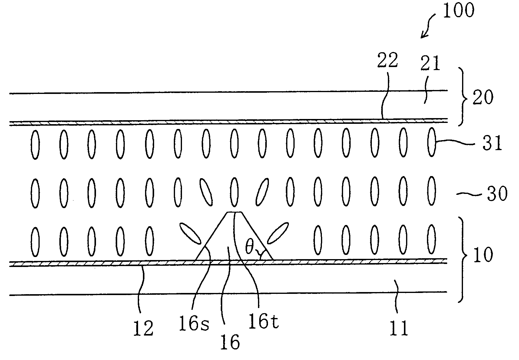
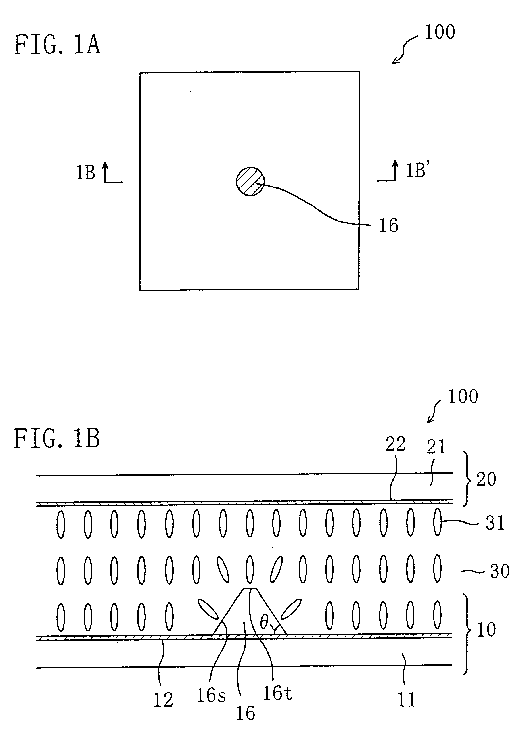
[0008] The liquid crystal display device of this invention includes a first substrate; a second substrate; a liquid crystal layer disposed between the first substrate and the second substrate; and a plurality of picture element regions each defined by a first electrode provided on a surface of the first substrate facing the liquid crystal layer and a second electrode provided on a surface of the second substrate facing the liquid crystal layer, and the first substrate has, on the surface thereof facing the liquid crystal layer, at least one first protrusion with an inclined side face correspondingly to each of the plurality of picture element regions, and a portion of the liquid crystal layer included in each of the plurality of picture element regions is in a substantially
vertical orientation state under application of no voltage, and includes at least a part of a first liquid crystal domain placed in a radially-inclined orientation state about the at least one first protrusion under voltage application, for producing a display by changing an orientation state of the liquid crystal layer in accordance with an applied voltage. Thus, the aforementioned object can be achieved.
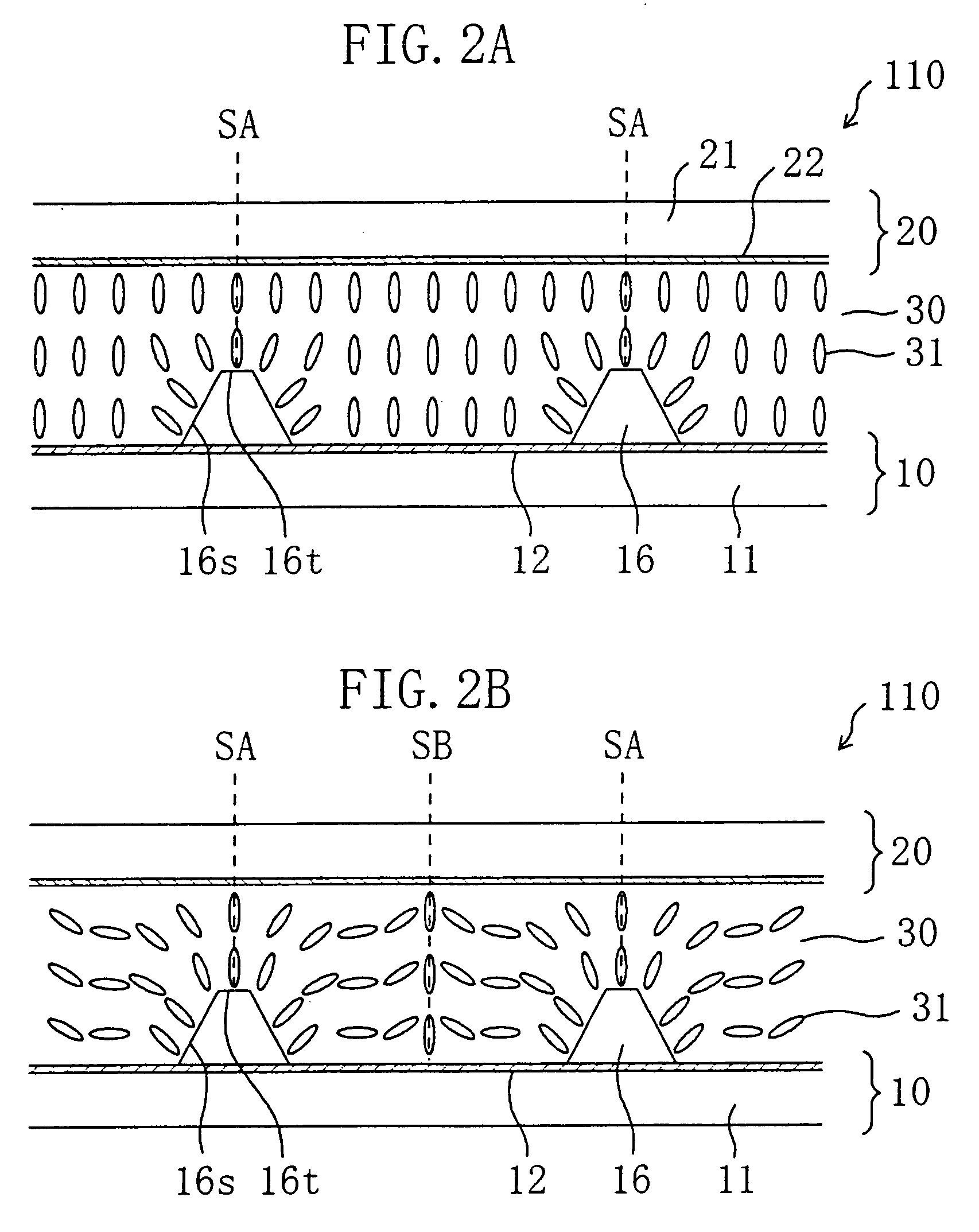
[0034] When a voltage is applied through the liquid crystal layer, liquid crystal molecules are inclined in directions matching with the orientation directions of the liquid crystal molecules inclined due to the influence (orientation-regulating force or the so-called anchoring effect) of the inclined side face of the protrusion. The extent of the inclination of the
liquid crystal molecule (i.e., the inclination angle) depends upon the strength of the
electric field, and as the
electric field is stronger, the
liquid crystal molecule is more largely inclined to be oriented in a direction closer to the horizontal direction. The inclination direction of the
liquid crystal molecule accords with the inclination direction of the liquid crystal molecule inclined radially about the protrusion by the anchoring effect of the inclined side face of the protrusion. Therefore, under voltage application, a liquid crystal domain in a radially-inclined orientation state is formed in the liquid crystal layer. In the liquid crystal domain placed in the radially-inclined orientation state, the liquid crystal molecules are oriented along all the
azimuth directions. As a result, the viewing angle characteristic of the liquid crystal display device can be improved in all the
azimuth directions.
[0039] Furthermore, as the area of the inclined side face of the protrusion is larger, the orientation-regulating force against the liquid crystal molecules is larger. For example, when the protrusion has a substantially cross-shaped cross-section, the area of the inclined side face can be comparatively increased, so as to comparatively increase the orientation-regulating force against the liquid crystal molecules. Therefore, the radially-inclined orientation can be further stabilized and the response speed can be increased. Moreover, when the protrusion has a substantially cross-shaped cross-section, the
transmittance and the
contrast ratio can be also improved by allowing the polarization axis directions of a pair of polarizing plates disposed in a crossed Nicols state to accord with the directions of the crossing lines of the cross (i.e., directions crossing each other at substantially right angles).
[0047] In particular, in a liquid crystal display device of the so-called multi-gap
system having different thicknesses of the liquid crystal layer within one picture element region, such as a transmission / reflection combination type liquid crystal display device having a transmission region and a reflection region in each picture element region (as disclosed in, for example, Japanese Laid-Open Patent Publication No. 11-101992), the orientation of the liquid crystal molecules is easily disturbed due to the influence of a level difference. Therefore, in such a liquid crystal display device, a liquid crystal domain with sufficiently stable radially-inclined orientation is difficult to form merely by using the orientation-regulating force caused by an inclined electric field. According to the invention, however, discontinuity in the orientation of the liquid crystal molecules owing to the level difference is suppressed by an electric field generated by an electrode covering the level difference, and the protrusion with an appropriate inclined side face is provided so as to form the center of the radially-inclined orientation by using the orientation-regulating force caused by the inclined side face. As a result, stable radially-inclined orientation can be realized. In particular, when the protrusion is surrounded with the level differences covered with the electrode, the discontinuity in the orientation of the liquid crystal molecules owing to the level differences can be effectively suppressed.
[0048] In this manner, the viewing angle characteristic of a liquid crystal display device can be improved by the present invention. Therefore, when the invention is applied to an
active matrix liquid crystal display device in particular, a display with very high quality can be produced.

