Liquid crystal display device having liquid crystal domains with radially-inclined orientation

a liquid crystal display and radial orientation technology, applied in the field of liquid crystal display devices, can solve the problems of super twist nematic, small production margin, narrow viewing angle, etc., and achieve the effect of effectively suppressing discontinuity in the orientation of liquid crystal molecules owing to level differences, stable radial orientation, and easy disturban

Inactive Publication Date: 2006-11-21
SHARP KK
View PDF36 Cites 29 Cited by
  • Summary
  • Abstract
  • Description
  • Claims
  • Application Information

AI Technical Summary

Benefits of technology

[0008]The present invention was devised to overcome the aforementioned disadvantages, and an object of the invention is providing a liquid crystal display device having a wide viewing angle characteristic and high display quality.
[0009]The liquid crystal display device of this invention includes a first substrate; a second substrate; a liquid crystal layer disposed between the first substrate and the second substrate; and a plurality of picture element regions each defined by a first electrode provided on a surface of the first substrate facing the liquid crystal layer and a second electrode provided on a surface of the second substrate facing the liquid crystal layer, and the first substrate has, on the surface thereof facing the liquid crystal layer, at least one first protrusion with an inclined side face correspondingly to each of the plurality of picture element regions, and a portion of the liquid crystal layer included in each of the plurality of picture element regions is in a substantially vertical orientation state under application of no voltage, and includes at least a part of a first liquid crystal domain placed in a radially-inclined orientation state about the at least one first protrusion under voltage application, for producing a display by changing an orientation state of the liquid crystal layer in accordance with an applied voltage. Thus, the aforementioned object can be achieved.
[0035]When a voltage is applied through the liquid crystal layer, liquid crystal molecules are inclined in directions matching with the orientation directions of the liquid crystal molecules inclined due to the influence (orientation-regulating force or the so-called anchoring effect) of the inclined side face of the protrusion. The extent of the inclination of the liquid crystal molecule (i.e., the inclination angle) depends upon the strength of the electric field, and as the electric field is stronger, the liquid crystal molecule is more largely inclined to be oriented in a direction closer to the horizontal direction. The inclination direction of the liquid crystal molecule accords with the inclination direction of the liquid crystal molecule inclined radially about the protrusion by the anchoring effect of the inclined side face of the protrusion. Therefore, under voltage application, a liquid crystal domain in a radially-inclined orientation state is formed in the liquid crystal layer. In the liquid crystal domain placed in the radially-inclined orientation state, the liquid crystal molecules are oriented along all the azimuth directions. As a result, the viewing angle characteristic of the liquid crystal display device can be improved in all the azimuth directions.
[0040]Furthermore, as the area of the inclined side face of the protrusion is larger, the orientation-regulating force against the liquid crystal molecules is larger. For example, when the protrusion has a substantially cross-shaped cross-section, the area of the inclined side face can be comparatively increased, so as to comparatively increase the orientation-regulating force against the liquid crystal molecules. Therefore, the radially-inclined orientation can be further stabilized and the response speed can be increased. Moreover, when the protrusion has a substantially cross-shaped cross-section, the transmittance and the contrast ratio can be also improved by allowing the polarization axis directions of a pair of polarizing plates disposed in a crossed Nicols state to accord with the directions of the crossing lines of the cross (i.e., directions crossing each other at substantially right angles).
[0048]In particular, in a liquid crystal display device of the so-called multi-gap system having different thicknesses of the liquid crystal layer within one picture element region, such as a transmission / reflection combination type liquid crystal display device having a transmission region and a reflection region in each picture element region (as disclosed in, for example, Japanese Laid-Open Patent Publication No. 11-101992), the orientation of the liquid crystal molecules is easily disturbed due to the influence of a level difference. Therefore, in such a liquid crystal display device, a liquid crystal domain with sufficiently stable radially-inclined orientation is difficult to form merely by using the orientation-regulating force caused by an inclined electric field. According to the invention, however, discontinuity in the orientation of the liquid crystal molecules owing to the level difference is suppressed by an electric field generated by an electrode covering the level difference, and the protrusion with an appropriate inclined side face is provided so as to form the center of the radially-inclined orientation by using the orientation-regulating force caused by the inclined side face. As a result, stable radially-inclined orientation can be realized. In particular, when the protrusion is surrounded with the level differences covered with the electrode, the discontinuity in the orientation of the liquid crystal molecules owing to the level differences can be effectively suppressed.
[0049]In this manner, the viewing angle characteristic of a liquid crystal display device can be improved by the present invention. Therefore, when the invention is applied to an active matrix liquid crystal display device in particular, a display with very high quality can be produced.

Problems solved by technology

Conventional twist nematic (TN) or super twist nematic (STN) liquid crystal display devices have, however, a disadvantage of a narrow viewing angle, and a variety of techniques have been developed for overcoming this disadvantage.
Although the lateral field method is one of the effective methods for attaining a wide viewing angle, the production margin is very small in the production process as compared with that of a general TN liquid crystal display device, and hence, there is a difficulty in stable production of this type of liquid crystal display devices.
When the surface of a vertical alignment film is subjected to a rubbing treatment, however, rubbing streaks are easily caused in a displayed image.
Therefore, this treatment is not suitable to mass-production.
However, the present inventors have found the following as a result of examination: The orientation state of a portion of a liquid crystal layer corresponding to the opening of the electrode is not specified in the methods disclosed in these publications, and the continuity of the orientation of the liquid crystal molecules is not sufficient.
Therefore, it is difficult to obtain a stable orientation state over an entire picture element, and hence, a displayed image becomes disadvantageously uneven.

Method used


Image

  • Liquid crystal display device having liquid crystal domains with radially-inclined orientation
  • Liquid crystal display device having liquid crystal domains with radially-inclined orientation
  • Liquid crystal display device having liquid crystal domains with radially-inclined orientation

Examples


embodiment 1

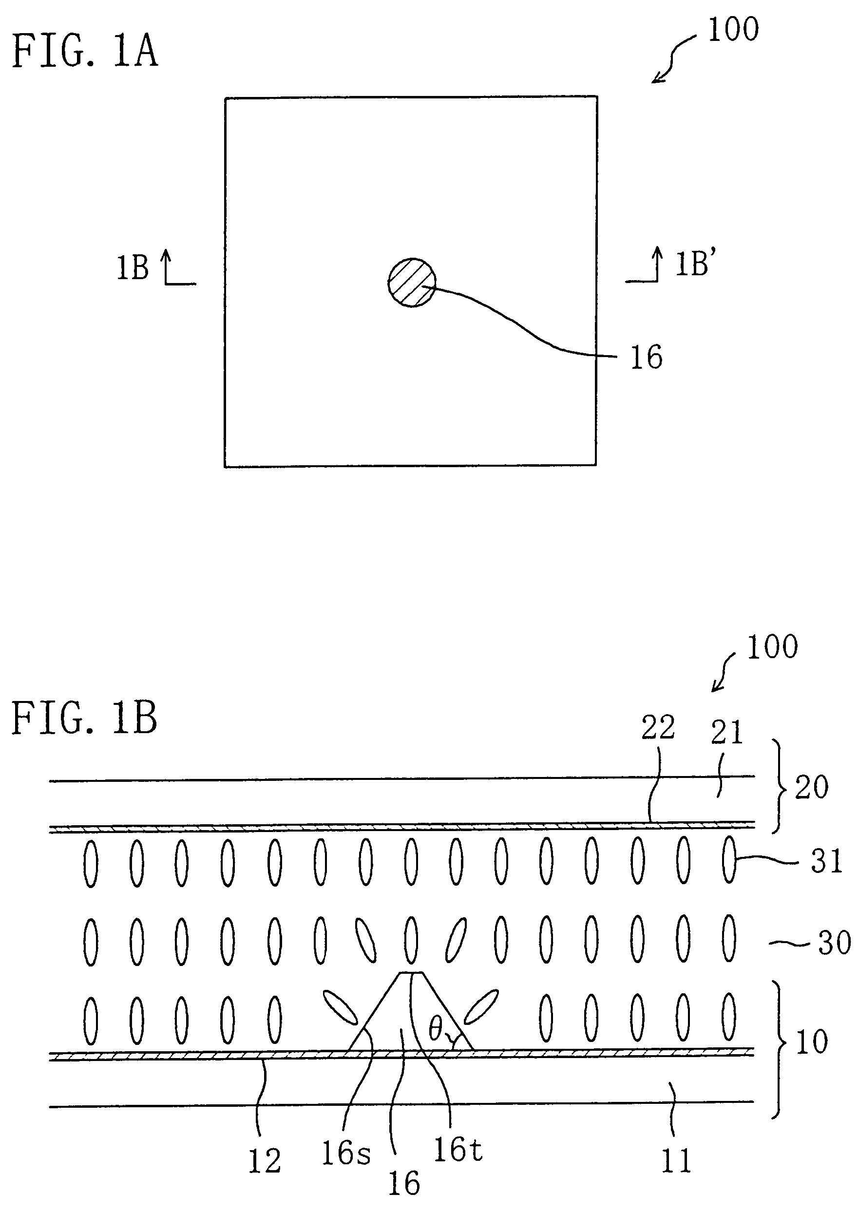
[0107]The liquid crystal display device of this invention is suitably used in an active matrix liquid crystal display device owing to its excellent display characteristic. Active matrix liquid crystal display devices using thin film transistors (TFTs) will be exemplified in the following preferred embodiments, which does not limit the invention. The invention is also applicable to an active matrix liquid crystal display device using MIMs and a passive matrix liquid crystal display device. Also, in the following embodiments, a transmission type liquid crystal display device and a transmission / reflection combination type liquid crystal display device are exemplified, which does not limit the invention. The invention is also applicable to a reflection type liquid crystal display device.

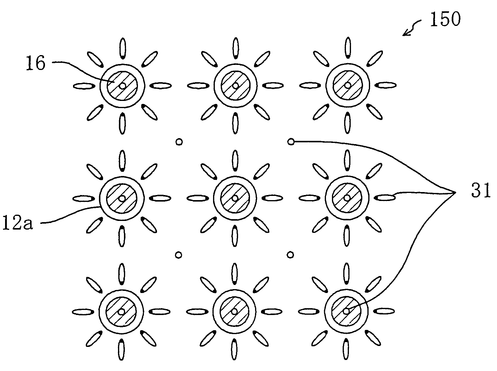
[0108]Herein, a region of a liquid crystal display device corresponding to a “picture element”, that is, a minimum unit of display, is designated as a “picture element region”. In a color liquid crystal ...

embodiment 2

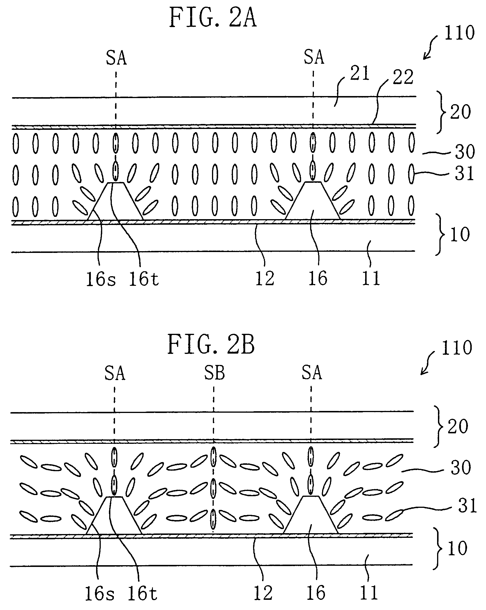
[0160]The stability of the radially-inclined orientation of liquid crystal molecules can be improved according to the invention, and therefore, when the invention is applied to a liquid crystal display device having a structure in which the orientation of liquid crystal molecules easily becomes unstable, the advantage can be remarkably exhibited. For example, in a liquid crystal display device of the so-called multi-gap system including a liquid crystal layer having different thicknesses in one picture element region, such as a transmission / reflection combination type liquid crystal display device having a transmission region and a reflection region in each picture element region, the orientation of liquid crystal molecules are easily disturbed due to a level difference, and hence, it is difficult to obtain stable radially-inclined orientation. For example, it has been found, as a result of examination made by the present inventors, that even when an opening is formed in the electro...


PUM

PropertyMeasurementUnit
angleaaaaaaaaaa
angleaaaaaaaaaa
angleaaaaaaaaaa

Abstract

The liquid crystal display device of this invention includes a vertical alignment type liquid crystal layer between a first substrate and a second substrate. A picture element region is defined by a first electrode provided on the surface of the first substrate facing the liquid crystal layer and a second electrode provided on the surface of the second substrate facing the liquid crystal layer. The first substrate has at least one first protrusion with an inclined side face on the surface thereof facing the liquid crystal layer in each of the plurality of picture element regions. A portion of the liquid crystal layer included in each of the plurality of picture element regions is in a substantially vertical orientation state under application of no voltage, and includes at least a part of a first liquid crystal domain placed in a radially-inclined orientation state about the first protrusion under voltage application. A display is produced by changing the orientation state of the liquid crystal layer in accordance with an applied voltage.

Description

[0001]This application is a Divisional of application Ser. No. 10 / 119,681 filed Apr. 11, 2002 now U.S. Pat. No. 6,788,375, the entire content of which is hereby incorporated herein by reference in this application.BACKGROUND OF THE INVENTION[0002]The present invention relates to a liquid crystal display device, and more particularly, it relates to a liquid crystal display device having a wide viewing angle characteristic and high display quality.[0003]Recently, a thin and light liquid crystal display device is used as a display device for a display of a personal computer or a display unit of portable information terminal equipment. Conventional twist nematic (TN) or super twist nematic (STN) liquid crystal display devices have, however, a disadvantage of a narrow viewing angle, and a variety of techniques have been developed for overcoming this disadvantage.[0004]A typical technique to improve the viewing angle characteristic of a TN or STN liquid crystal display device is a method ...

Claims


Application Information

Patent Timeline
Patent Type & Authority Patents(United States)
IPC IPC(8): G02F1/1337G02F1/1333G02F1/1335G02F1/1368G02F1/139
CPCG02F1/133555G02F1/133707G02F1/1393A47G1/0616A47G2200/06B82Y40/00
Inventor OGISHIMA, KIYOSHIKUBO, MASUMI
Owner SHARP KK
Why Eureka
Try Eureka