Liquid crystal display device

a display device and liquid crystal technology, applied in static indicating devices, instruments, non-linear optics, etc., can solve problems such as making the observer feel unnatural, and achieve the effect of wide viewing angle characteristics and high display quality

Inactive Publication Date: 2008-06-19
SHARP KK
View PDF23 Cites 2 Cited by
  • Summary
  • Abstract
  • Description
  • Claims
  • Application Information

AI Technical Summary

Benefits of technology

[0009]The present invention was devised to overcome the aforementioned disadvantages, and an object of the present invention is providing a liquid crystal display device with high display quality that has a wide viewing angle characteristic and can provide display free from unnaturalness.

Problems solved by technology

Therefore, the gray-scale characteristic greatly varies with the angle at which the observer views the display plane, and this makes the observer feel unnatural.

Method used


Image

  • Liquid crystal display device
  • Liquid crystal display device
  • Liquid crystal display device

Examples


embodiment 1

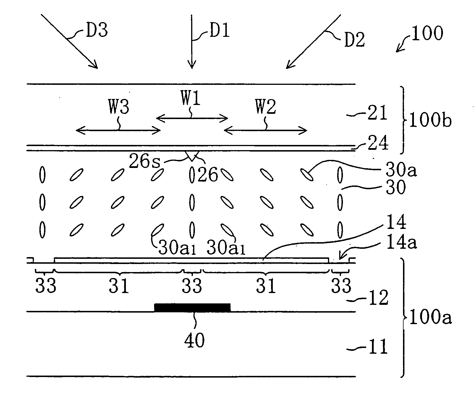
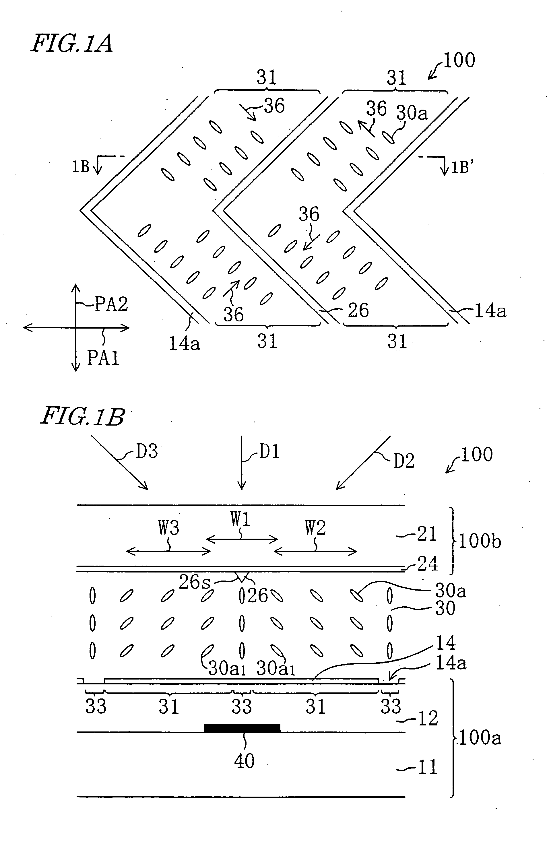
[0040]The structure of a liquid crystal display device 100 of Embodiment 1 of the present invention will be described with reference to FIGS. 1A and 1B. Note that in the following description, color filters and a black matrix are ignored for simplification. Throughout the drawings, components having the same functions are denoted by the same reference numerals and are not described repeatedly. FIG. 1A is a top view of the liquid crystal display device 100 as viewed in the direction normal to the substrate plane, and FIG. 1B is a cross-sectional view taken along line 1B-1B′ in FIG. 1A. FIGS. 1A and 1B show the state under application of a voltage across the liquid crystal layer.

[0041]The liquid crystal display device 100 includes an active matrix substrate (hereinafter, called a “TFT substrate”) 10a, a counter substrate (also called a “color filter substrate”) 10b, and a vertical alignment type liquid crystal layer 30 disposed between the TFT substrate 10a and the counter substrate 1...

embodiment 2

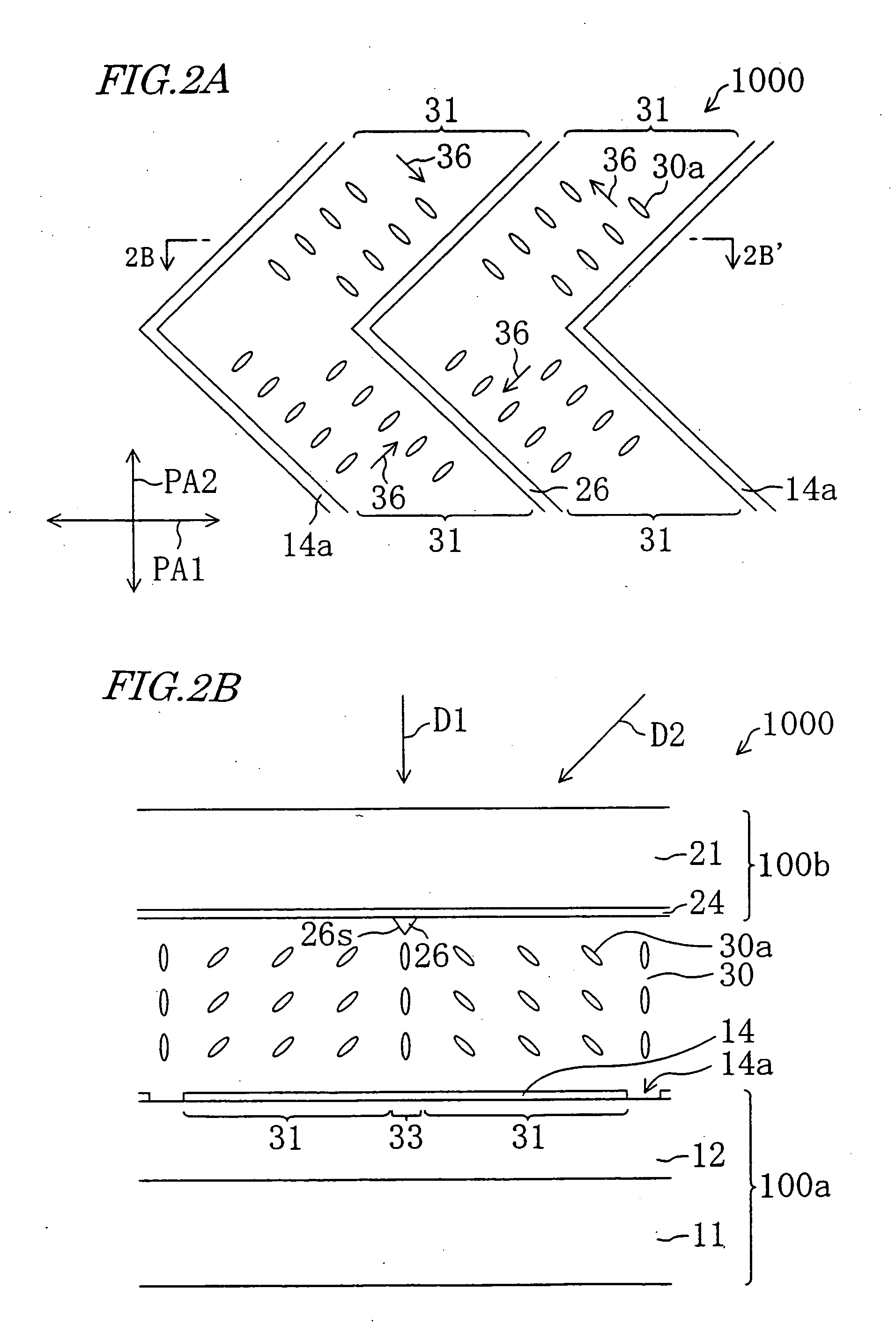
[0091]FIGS. 9A and 9B show a liquid crystal display device 200 of Embodiment 2 according to the present invention, where FIG. 9A is a top view of the liquid crystal display device 200 as viewed in the direction normal to the substrate, and FIG. 9B is a cross-sectional view taken along line 9B-9B′ in FIG. 9A. FIGS. 9A and 9B show the state under application of a voltage across the liquid crystal layer.

[0092]In the liquid crystal display device 100 of Embodiment 1, each picture-element region was divided into four in terms of the orientation so that the liquid crystal molecules are oriented in four directions. In the liquid crystal display device 200 of Embodiment 2, each picture-element region is divided into an infinite number in terms of the orientation so that the liquid crystal molecules are oriented in all directions.

[0093]A TFT substrate 200a of the liquid crystal display device 200 includes picture-element electrodes 14 having openings 14a as an orientation-regulating structur...

embodiment 3

[0109]The structure of a liquid crystal display device 300 of Embodiment 3 according to the present invention will be described with reference to FIGS. 12A and 12B. FIG. 12A is a top view of the liquid crystal display device 300 as viewed in the direction normal to the substrate, and FIG. 12B is a cross-sectional view taken along line 12B-12B′ in FIG. 12A. FIGS. 12A and 12B show the state under application of a voltage across the liquid crystal layer.

[0110]The liquid crystal display device 300 of Embodiment 3 is the same in construction as the liquid crystal display device 100 of Embodiment 1 except for the position of the light-shield layers.

[0111]A counter substrate 300b of the liquid crystal display device 300 has a light-shield layer 41 in each of a plurality of picture-element regions. The light-shield layer 41 is formed to overlap (lie above) a specific region of the liquid crystal layer 30 as will be described later.

[0112]In the liquid crystal display device 300 in which each...


PUM

PropertyMeasurementUnit
angleaaaaaaaaaa
widthaaaaaaaaaa
widthaaaaaaaaaa

Abstract

The liquid crystal display device of this invention includes a first substrate, a second substrate, and a vertical alignment type liquid crystal layer including liquid crystal molecules having negative dielectric anisotropy disposed between the two substrates. In each of a plurality of picture-element regions, the liquid crystal layer has a plurality of liquid crystal regions different in the direction in which liquid crystal molecules tilt upon application of a voltage. At least one of the first and second substrates has a light-shield layer overlapping at least part of boundary region defined as regions separating the plurality of liquid crystal regions from each other. The part of the boundary region overlapping the light-shield layer is a region permitting liquid crystal molecules surrounding the region to tilt so that the ends of the liquid crystal molecules closer to the substrate having the light-shield layer go away from the region upon application of a voltage.

Description

BACKGROUND OF THE INVENTION[0001]The present invention relates to a liquid crystal display device, and more particularly, to a liquid crystal display device having a wide viewing angle characteristic and providing high quality display.[0002]The liquid crystal display device is a flat display device having excellent features of being thin, light in weight and low in power consumption. However, the liquid crystal display device has a shortcoming of being large in “viewing angle dependence” in which the display state changes with the direction in which the display device is observed. A main cause for the large viewing angle dependence of the liquid crystal display device is that liquid crystal molecules having uniaxial optical anisotropy are oriented uniformly in the display plane.[0003]To improve the viewing angle characteristic of the liquid crystal display device, an orientation division method is effective, in which a plurality of regions different in orientation states are formed ...

Claims


Application Information

Patent Timeline
Patent Type & Authority Applications(United States)
IPC IPC(8): G02F1/1337G02F1/1335G02F1/133G02F1/1333G02F1/1343G02F1/139
CPCG02F1/133512G02F1/1393G02F1/133707G02F1/133
Inventor OGISHIMA, KIYOSHIKUBO, MASUMI
Owner SHARP KK
Why Eureka
Try Eureka