Liquid crystal display device

a liquid crystal display and display device technology, applied in semiconductor devices, instruments, electrical devices, etc., can solve the problems of super twist nematic, small production margin, narrow viewing angle, etc., to improve the response characteristic, improve the transmittance, and improve the stability of the radially inclined orientation of the liquid crystal domain formed in the solid portion.

Inactive Publication Date: 2013-10-01
SHARP KK
View PDF42 Cites 0 Cited by
  • Summary
  • Abstract
  • Description
  • Claims
  • Application Information

AI Technical Summary

Benefits of technology

[0008]The present invention was devised to overcome the aforementioned disadvantages, and an object of the invention is providing a liquid crystal display device having a wide viewing angle characteristic and high display quality.

Problems solved by technology

Conventional twist nematic (TN) or super twist nematic (STN) liquid crystal display devices have, however, a disadvantage of a narrow viewing angle, and various techniques have been developed for overcoming this disadvantage.
Although the lateral field method is one of effective methods for increasing the viewing angle, the production margin is very small in the production process as compared with that of a general TN liquid crystal display device, and hence, there is a difficulty in stable production of this type of liquid crystal display devices.
When the surface of a vertical alignment film is subjected to a rubbing treatment, however, rubbing streaks are easily caused in a displayed image.
Therefore, this treatment is not suitable to mass-production.
However, the present inventors have found the following as a result of examination: The orientation state of a region of a liquid crystal layer corresponding to the opening of the electrode is not specified in the methods disclosed in these publications, and the continuity of the orientation of the liquid crystal molecules is not sufficient.
Therefore, it is difficult to obtain a stable orientation state over an entire picture element, and hence, a displayed image becomes disadvantageously uneven.

Method used


Image

  • Liquid crystal display device
  • Liquid crystal display device
  • Liquid crystal display device

Examples


embodiment 1

[0100]First, the electrode structure of a liquid crystal display device of this invention and the function thereof, will be described. The liquid crystal display device of this invention is suitably used in an active matrix liquid crystal display device owing to its excellent display characteristic. Active matrix liquid crystal display devices using thin film transistors (TFTs) will be exemplified in the following preferred embodiments, which does not limit the invention. The invention is also applicable to an active matrix liquid crystal display device using MIMs and a passive matrix liquid crystal display device. Also, in the following embodiments, transmission type liquid crystal display devices are exemplified, which does not limit the invention. The invention is also applicable to a reflection type liquid crystal display device and a transmission / reflection type liquid crystal display device described later.

[0101]Herein, a region of a liquid crystal display device corresponding...

embodiment 2

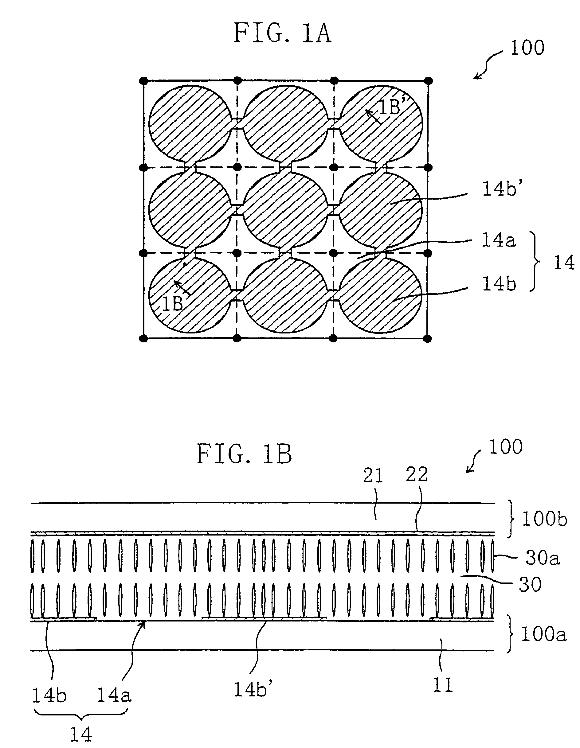
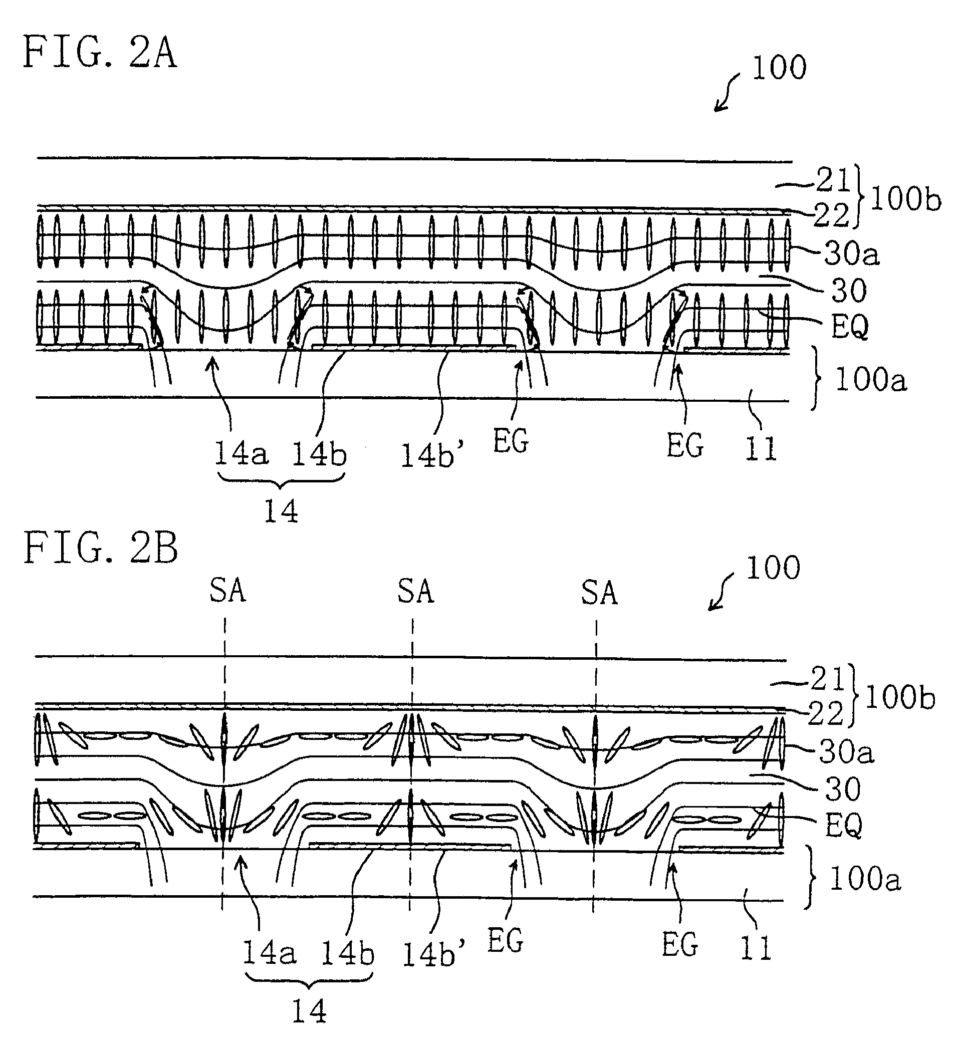
[0174]The structure of one picture element region of a liquid crystal display device 200 according to Embodiment 2 of the invention will now be described with reference to FIGS. 13A and 13B. In all the drawings referred to below, like reference numerals are used to refer to like elements having substantially the same functions as those of the liquid crystal display device 100, so as to omit the description. FIG. 13A is a top view seen from the substrate normal direction, and FIG. 13B is a cross-sectional view taken along line 13B-13B′ of FIG. 13A. FIG. 13B shows a state where no voltage is applied through the liquid crystal layer.

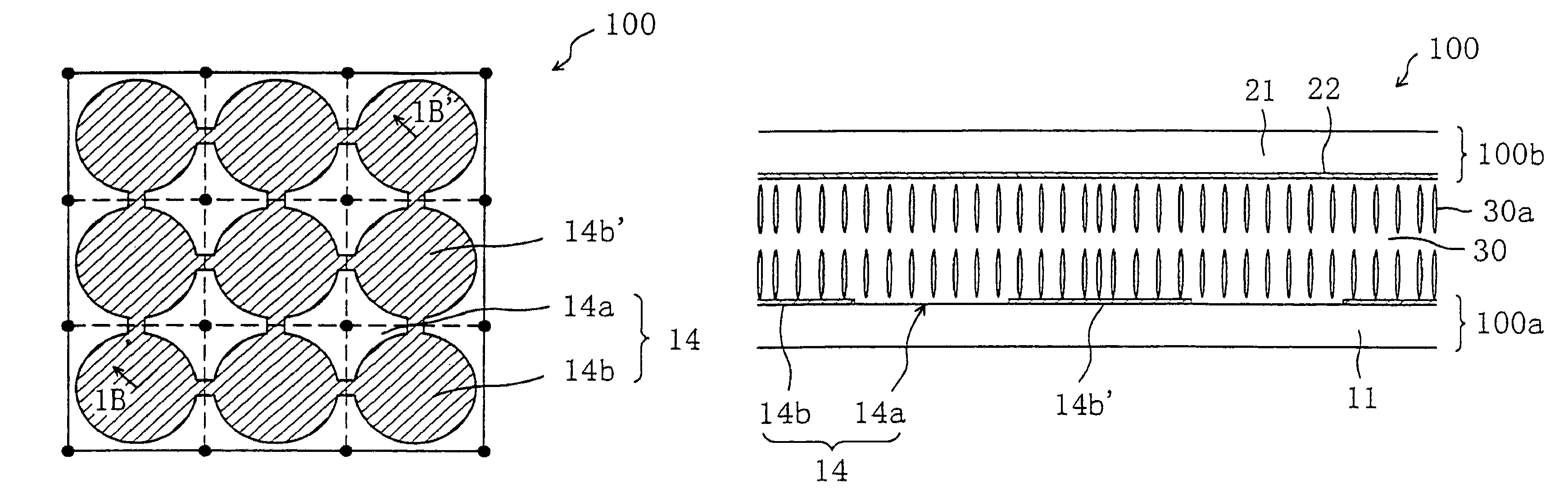
[0175]As shown in FIGS. 13A and 13B, the liquid crystal display device 200 is different from the liquid crystal display device 100 of Embodiment 1 shown in FIGS. 1A and 1B in a TFT substrate 200a including a protrusion 40 within each opening 14a of the picture element electrode 14. On the protrusion 40, a vertical alignment film (not shown) is provided.

[017...


PUM


Abstract

The liquid crystal display device of this invention includes picture element regions each defined by a first electrode provided on a first substrate and a second electrode provided on a second substrate so as to oppose the first electrode via a liquid crystal layer sandwiched therebetween. In each of the picture element regions, the first electrode includes a solid portion and a nonsolid portion. The liquid crystal display device further includes a pair of polarizing plates disposed with polarization axes thereof crossing each other substantially perpendicularly. The polarization axis of one of the pair of polarizing plates is substantially parallel to a direction in which the solid portion extends. When a voltage is applied between the first electrode and the second electrode, in each of the picture element regions, liquid crystal molecules of the liquid crystal layer are in a radially-inclined orientation state.

Description

[0001]This application is a Continuation of Ser. No. 12 / 656,129, filed Jan. 19, 2010, now U.S. Pat. No. 8,053,775 which is a Continuation of Ser. No. 11 / 507,516, filed Aug. 22, 2006 (now U.S. Pat. No. 7,755,087), which is a Continuation of Ser. No. 10 / 839,333, filed May 6, 2004, (now U.S. Pat. No. 7,145,624), which is a divisional of application Ser. No. 09 / 923,344 filed Aug. 8, 2001, (now U.S. Pat. No. 7,215,395) the entire contents of which are hereby incorporated herein by reference in this application.BACKGROUND OF THE INVENTION[0002]The present invention relates to a liquid crystal display device, and more particularly, it relates to a liquid crystal display device having a wide viewing angle characteristic capable of producing a high quality display.[0003]Recently, a thin and light liquid crystal display device is used as a display device for a display of a personal computer and a display unit of portable information terminal equipment. Conventional twist nematic (TN) or super...

Claims


Application Information

Patent Timeline
Patent Type & Authority Patents(United States)
IPC IPC(8): H01L29/04
CPCG02F1/133707G02F1/1393
Inventor KUBO, MASUMIYAMAMOTO, AKIHIROOCHI, TAKASHIYAMAGUCHI, TETSUHIROYAMADA, NAOSHIMORISHITA, KATSUHIKOOGISHIMA, KIYOSHIMAEKAWA, KAZUHIRO
Owner SHARP KK
Why Eureka
Try Eureka