Matrix-type liquid crystal display device

a liquid crystal display and matrix-type technology, applied in non-linear optics, instruments, optics, etc., can solve the problems of generating moire, concentric display unevenness, etc., and achieve the effect of broad color reproducibility and wide viewing angle characteristics

Active Publication Date: 2010-10-05
FUJIFILM CORP
View PDF14 Cites 2 Cited by
  • Summary
  • Abstract
  • Description
  • Claims
  • Application Information

AI Technical Summary

Benefits of technology

[0011]However, in a liquid crystal display device having the above-described scattering film, when an optical member having a light-condensing function is disposed between the backlight and the liquid crystal layer, a fringe-like or concentric display unevenness called moire is generated due to optical interference with the pixel of the liquid crystal layer. An aspect of the present invention is to eliminate this problem of interference pattern and provide a liquid crystal display device endowed with wide viewing angle characteristics and broad color reproducibility.

Problems solved by technology

However, in a liquid crystal display device having the above-described scattering film, when an optical member having a light-condensing function is disposed between the backlight and the liquid crystal layer, a fringe-like or concentric display unevenness called moire is generated due to optical interference with the pixel of the liquid crystal layer.

Method used


Image

  • Matrix-type liquid crystal display device
  • Matrix-type liquid crystal display device
  • Matrix-type liquid crystal display device

Examples


example 1

(1) Coating of Light-Scattering Layer

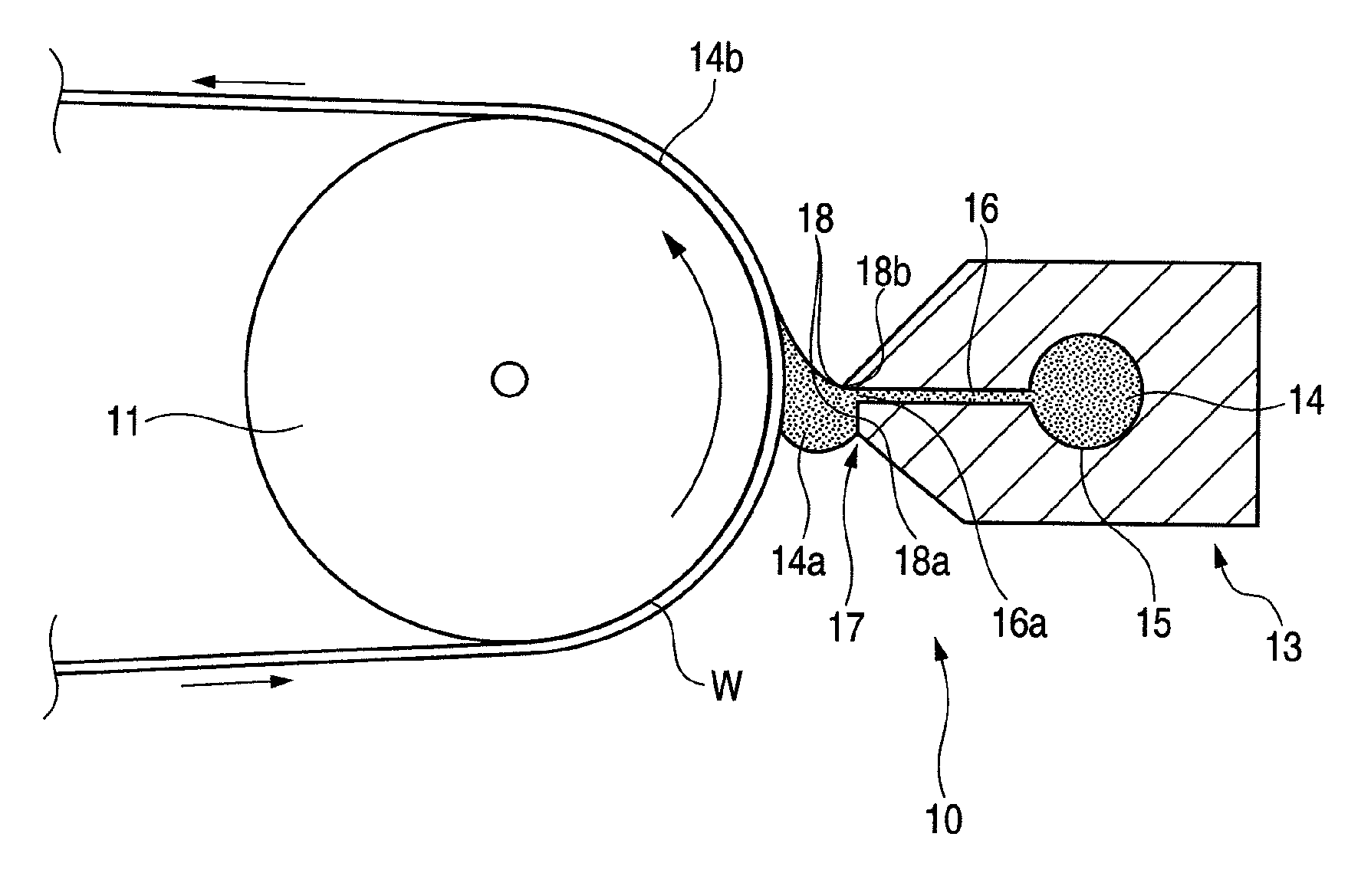
[0174]A 80 μm-thick triacetyl cellulose film (TAC-TD80U, produced by Fujifilm Corp., refractive index: 1.49) in a roll form was unrolled as the transparent support, and Coating Solution A for Light-Scattering Layer was coated thereon by the die coating method shown in Constitution of Apparatus and Coating Conditions below and after drying at 30° C. for 15 seconds and at 90° C. for 20 seconds, irradiated with an ultraviolet ray at an irradiation dose of 90 mJ / cm2 by using an air-cooled metal halide lamp (manufactured by Eye Graphics Co., Ltd.) of 160 W / cm under nitrogen purging (to an oxygen concentration of 0.05 vol %) to cure the coated layer, whereby a 12 μm-thick light-scattering layer having an antiglare property was formed. The resulting film was taken up.

Basic Conditions (reference to FIG. 6):

[0175]A slot die 13 where the upstream lip land length IUP is 0.5 mm, the downstream lip land length ILO is 50 μm, the length of the opening of the sl...

example 2

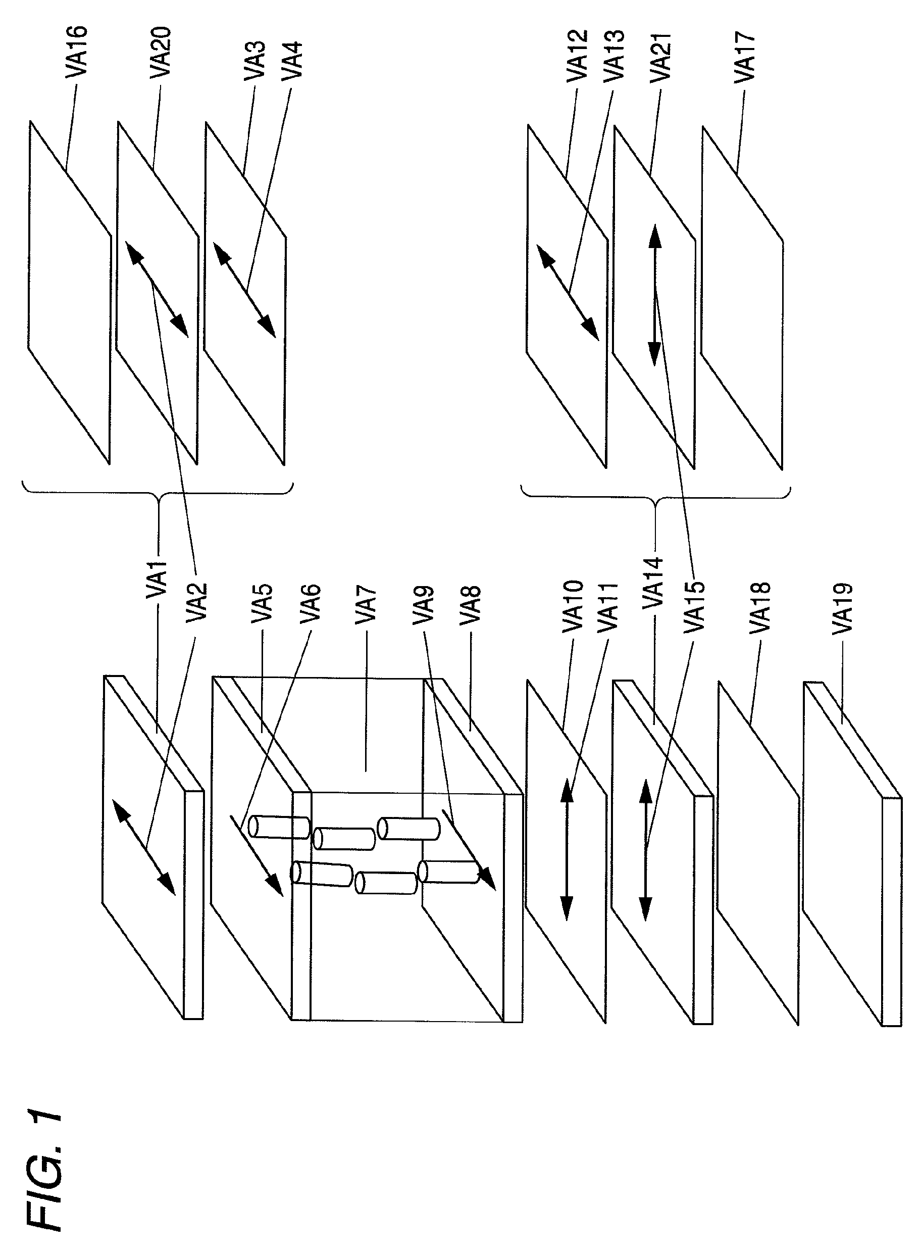
[0216]The construction was the same as in Example 1 except that in Example 1, the surface of the lower polarizing plate was not changed from that of the commercial product and Sample 1-1 was disposed as a light-diffusing film between the light-condensing film (VA18) and the lower polarizing plate surface film (VA17). The level of disturbing reflection was “A”, the level of glittering was “A”, and the level of moire was “A”.

example 3

[0217]The construction was the same as in Example 1 except that in Comparative Example 2, the axis in the groove direction of the prism sheet was arranged to cross at 5° from the horizontal direction. The level of disturbing reflection was “A”, the level of glittering was “A”, and the level of moire was “B”.


PUM

PropertyMeasurementUnit
incident angleaaaaaaaaaa
angleaaaaaaaaaa
crossing angleaaaaaaaaaa

Abstract

A matrix-type liquid crystal display device, includes: a liquid crystal panel including: a pair of substrates disposed to face each other with at least one of the pair of substrates having an electrode; a liquid crystal layer interposed between the pair of substrates; a pair of polarizing plates disposed to sandwich the liquid crystal layer, each having a polarizing film and a protective film provided directly or indirectly on at least one surface of the polarizing film; and an optically compensatory film disposed in at least one of spaces between the liquid crystal layer and the pair of polarizing films; a backlight comprising a light source; a first optical member having a light-condensing property; and a second optical member having a surface scattering function.

Description

BACKGROUND OF THE INVENTION[0001]1. Field of the Invention[0002]The present invention relates to a matrix-type liquid crystal display device.[0003]2. Description of the Related Art[0004]As regards the display device used, for example, as a monitor for OA devices such as word processor, notebook computer and personal computer, as well as in a mobile device or a television, CRT (cathode ray tube) has been heretofore mainly used. In recent years, a liquid crystal display is becoming widely used instead of CRT because of its small thickness, light weight and low power consumption. The liquid crystal display device comprises a liquid crystal cell and a polarizing plate. The polarizing plate is usually composed of a protective film and a polarizing film and is obtained by dyeing a polarizing film comprising a polyvinyl alcohol film with iodine, stretching the film and stacking a protective film on both surfaces of the film. In a transmission-type liquid crystal display device, this polari...

Claims


Application Information

Patent Timeline
Patent Type & Authority Patents(United States)
IPC IPC(8): G02F1/1335
CPCG02F1/133606G02F1/1393G02F2001/133507G02F1/133507
Inventor WATANABE, JUNHIRAKATA, JUNICHI
Owner FUJIFILM CORP
Why Eureka
Try Eureka