Reciprocal-movement power tool

a reciprocal motion and power tool technology, applied in the direction of liquid/fluent solid measurement, liquid transfer device, interengaging clutch, etc., can solve the problems of user's hand fatigue, sparks flying around, dust and chips scattered around, etc., and achieve the effect of providing inexpensively and simple configuration

Inactive Publication Date: 2005-09-06
HITACHI KOKI CO LTD
View PDF10 Cites 26 Cited by
  • Summary
  • Abstract
  • Description
  • Claims
  • Application Information

AI Technical Summary

Benefits of technology

[0019]As described above, the present invention enables a reciprocal-mov...

Problems solved by technology

However, grinding dust and chips may be scattered around ambient objects and sparks may fly around due to high speed rotation of the grinding stone.
On the other hand, there are problems in that the user's hand can become tired because the device is manually operated and also cutting takes a long time to complete.
First, a large space is required for setting the angle iron between the reception plate and the movable blade. Because the mo...

Method used


Image

  • Reciprocal-movement power tool
  • Reciprocal-movement power tool
  • Reciprocal-movement power tool

Examples


Embodiment Construction

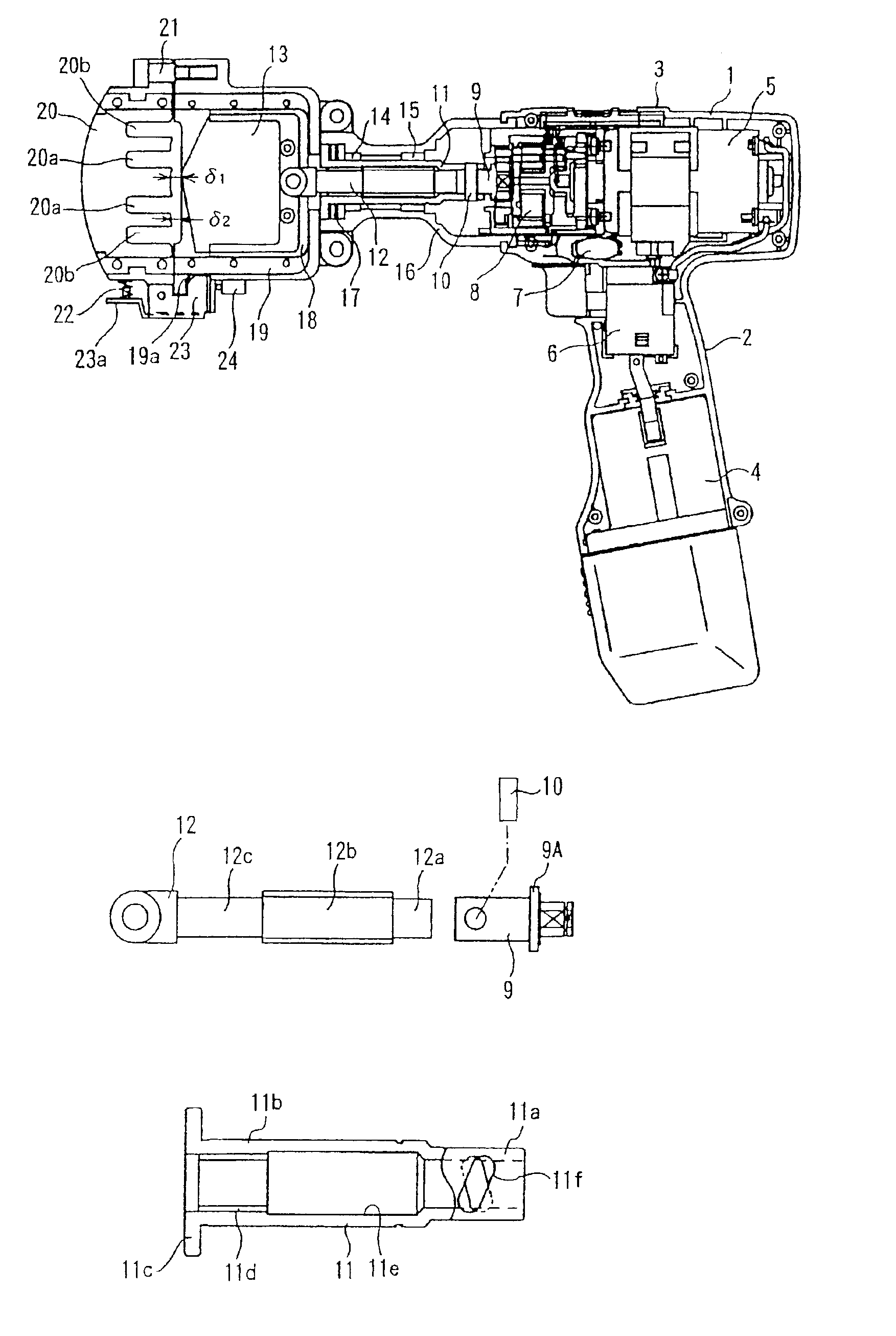
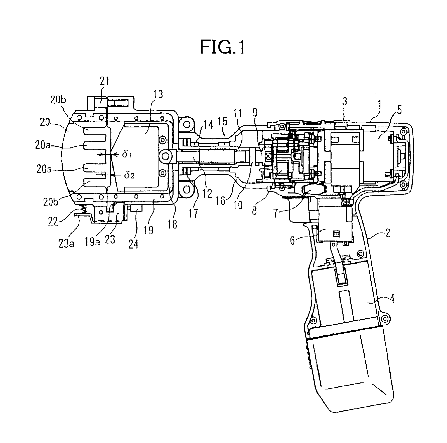
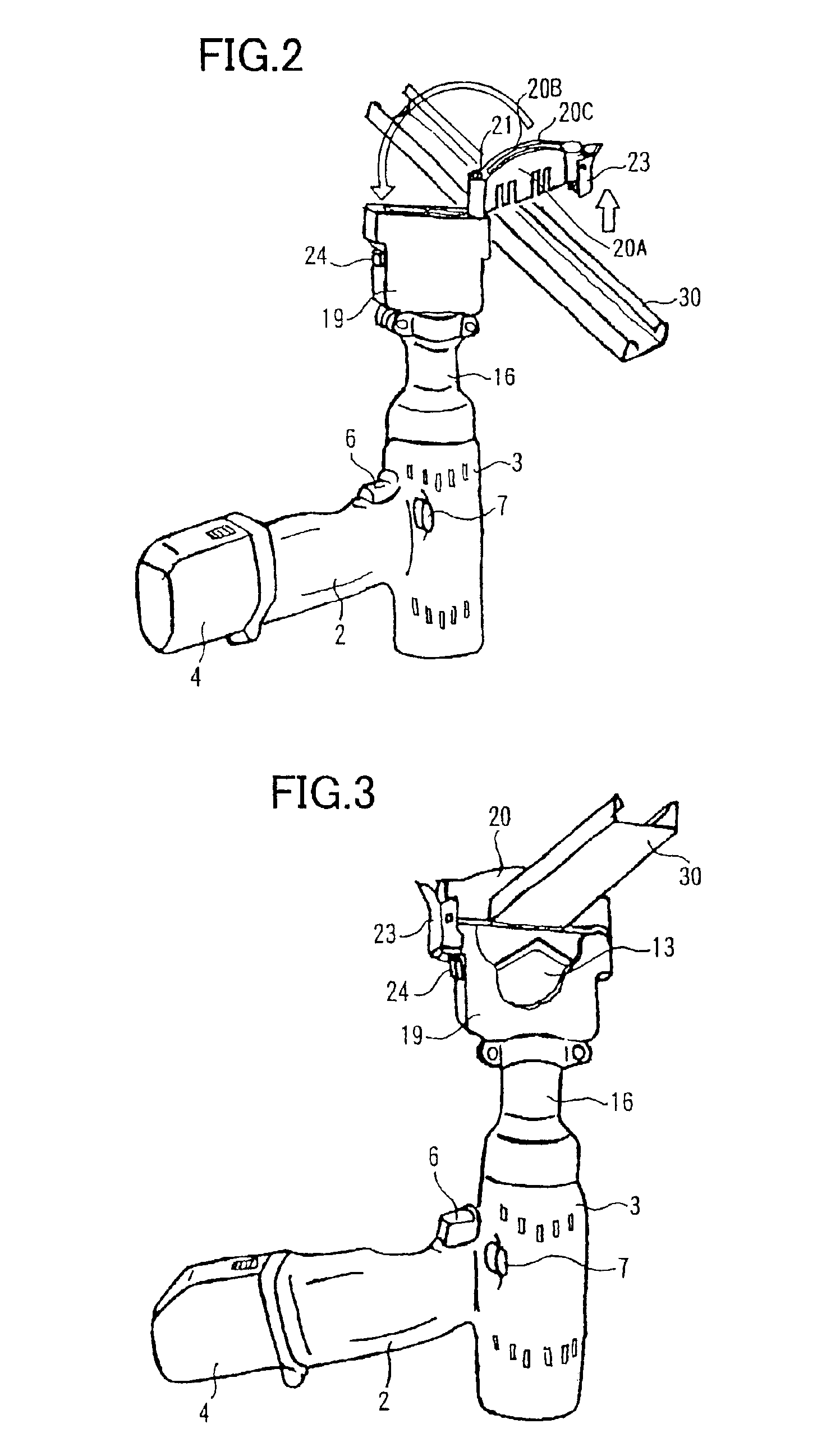
[0036]Below an angle iron cutter according to an embodiment of the present invention will be described with reference to FIGS. 1 to 6. A main body of the cutter includes a motor chamber 1 that houses a motor 5, a housing 3 disposed in a T-shape in combination with a handle 2, and a gear cover 16. A storage battery 4 is detachably provided to the lower portion of the handle 2. A main switch 6 and a push button 7 are provided to the handle 2. The main switch 6 is for starting and stopping application of electric current to the motor 5. The push button 7 is for switching the polarity of voltage supplied to the motor 5 to change the rotational direction of the motor 5.

[0037]The gear cover 16 is fixed to the front end of the housing 3. A holder 19 is fixed to the front end of the gear cover 16. Three stage planetary gear train 8, a joint spindle 9, a pin 10, a screw shaft 11, and a shuttle screw 12 are provided within the housing 3 and the gear cover 16. The joint spindle 9 configures an...


PUM

PropertyMeasurementUnit
Angleaaaaaaaaaa
Levelaaaaaaaaaa

Abstract

A reciprocal-movement power tool includes a movable blade reciprocally movably provided on a main body. A receiving plate that supports an angle iron to be cut is supported on the main body at a position in front of the movable blade. The movable blade is fixed on a front tip of a rod-shaped shuttle screw. The shuttle screw moves back and forth in the axial direction within a tubular screw shaft. The screw shaft is carved with a female screw portion and is rotated through a joint spindle that is deceleratingly rotated upon rotation of the motor through a deceleration means. The shuttle screw has a male screw portion that is threadingly engageable with the female screw portion.

Description

TECHNICAL FIELD[0001]The present invention relates to an electrically powered reciprocal-movement tool, and more particularly to a reciprocal-movement power tool that can be used as a cutting device, a crimp tool and a calking gun. The cutting device is adapted for cutting an angle iron such as light weight ceiling bars, which are steel furrings for wall and ceiling in buildings. The crimp tool is adapted for crimping terminals, and the calking gun is adapted for ejecting calking material. Hereinafter, a reciprocal-movement tool will be described in the form of a cutting device for cutting the steel furrings for wall and ceiling in buildings.BACKGROUND ART[0002]In building construction, there is a light-weight steel frame ceiling made by suspending hanging bolts from a ceiling slab, using the hanging bolt to assemble ceiling bars and ceiling bar supports into a lattice, and suspending boards on the lattice. The ceiling bars and ceiling bar supports used in this ceiling are defined b...

Claims


Application Information

Patent Timeline
IPC IPC(8): B25B27/02B25B27/14B25B27/10B23D15/04B23D15/12B23D15/00B23D29/00
CPCB23D15/04B23D15/12B25B27/10B25B27/146B23D29/00Y10T74/19702Y10T83/9454Y10T83/8847Y10T83/693
Inventor YOSHIMIZU, CHIKAIKIKUMOTO, MASAOSHIMADA, TAKAHIKO
Owner HITACHI KOKI CO LTD
Why Eureka
Try Eureka