Fuel control device for a combustion engine

a technology of control device and combustion engine, which is applied in the direction of machines/engines, combustible gas chemical modification, and combustion gas purification/modification, etc., can solve the problem of mootness of engine running utilizing a variety of different fuels, and achieve the effect of large force, improved layout design, and expanded control range of the shutoff valv

Inactive Publication Date: 2006-10-26
WALBRO ENGINE MANAGEMENT
View PDF6 Cites 29 Cited by
  • Summary
  • Abstract
  • Description
  • Claims
  • Application Information

AI Technical Summary

Benefits of technology

[0008] Moreover, since the vacuum diaphragm is provided externally of the fuel metering chamber associated with the actuator of the flow valve, freedom in layout design can be improved and the size of the vacuum diaphragm can be selected at wi11 without regard to the size of the fuel metering chamber. Therefore, even when the vacuum pressure is small, a relatively large force can be produced, and this expands the range of the control of the shutoff valve. For instance, the shutoff valve can be opened even while the vacuum pressure is relatively small. Whereas, if the vacuum diaphragm of the shutoff valve actuator is provided in the metering chamber of the flow valve actuator, an increase in the size of the vacuum diaphragm necessarily increases the overall size of the fuel metering apparatus.
[0009] Other advantages of the present invention include a fuel control device that facilitates selection of fuel-types, can be mounted to an engine capable of running on any one of a plurality of fuels, and a fuel metering apparatus that is easily adapted to different specifications so as to meet the needs of different engines while utilizing an identical structure. Other advantages include a robust shutoff valve actuator that is generally free of air leakage concerns about the elongated member, and a device that automatically shuts off fuel flow when the engine is stopped thereby conserving fuel, a device that is simple in design and inexpensive enough to warrant use on small engine applications, and in service has a long and useful life. Of course, other advantages may be realized and devices incorporating the present invention may achieve some, all, or none of these advantages.

Problems solved by technology

Unfortunately, propane gas and butane gas have different calorific values and therefore must be provided to the engine at specific pre-determined pressures dependent upon the type of gas.
Because specific gasses must flow at specific pressures the ability of an engine to run utilizing a variety of different fuels is somewhat moot because an easy and economical means of varying fuel supply pressures to correspond to different gas types is not available.

Method used


Image

  • Fuel control device for a combustion engine
  • Fuel control device for a combustion engine
  • Fuel control device for a combustion engine

Examples


Embodiment Construction

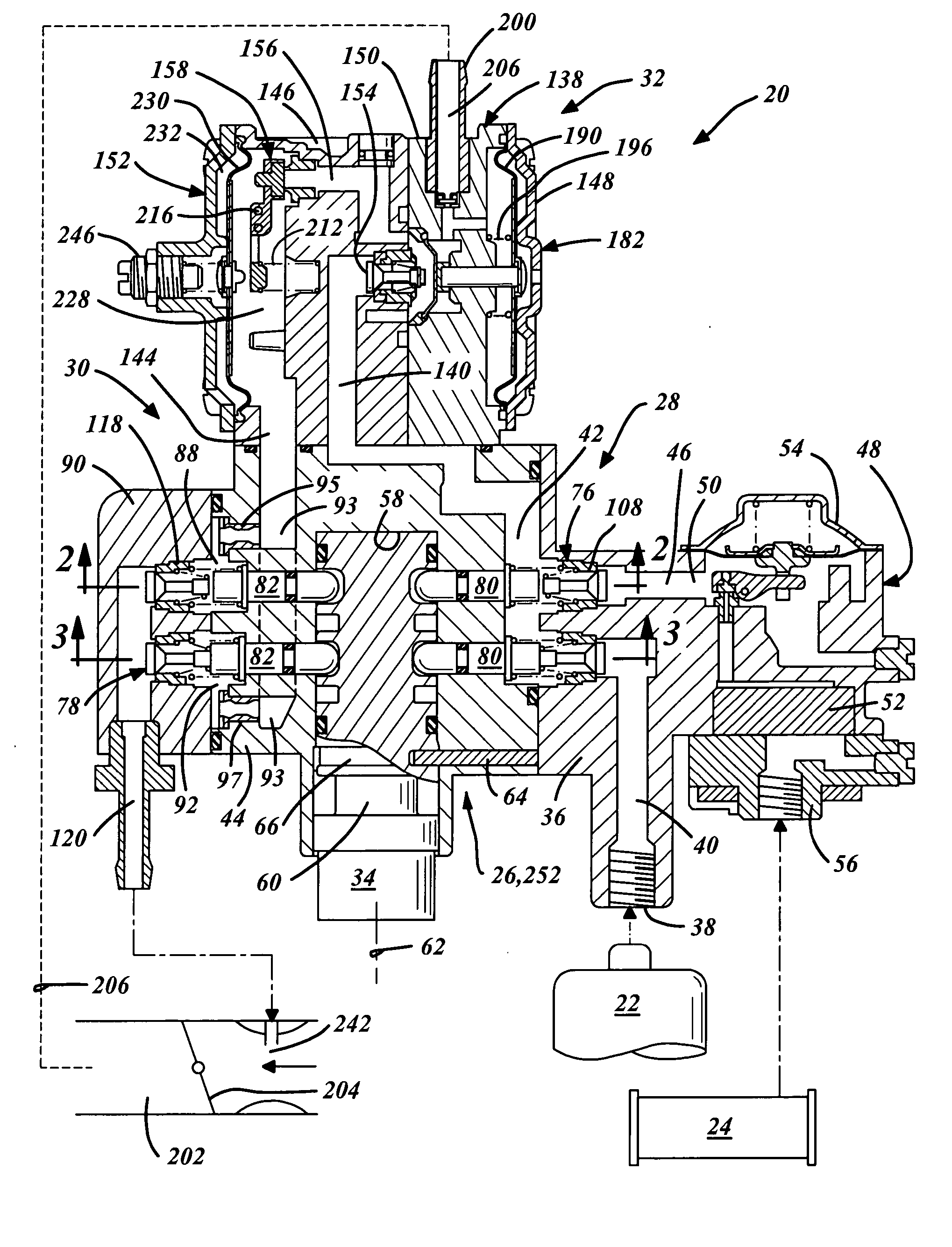
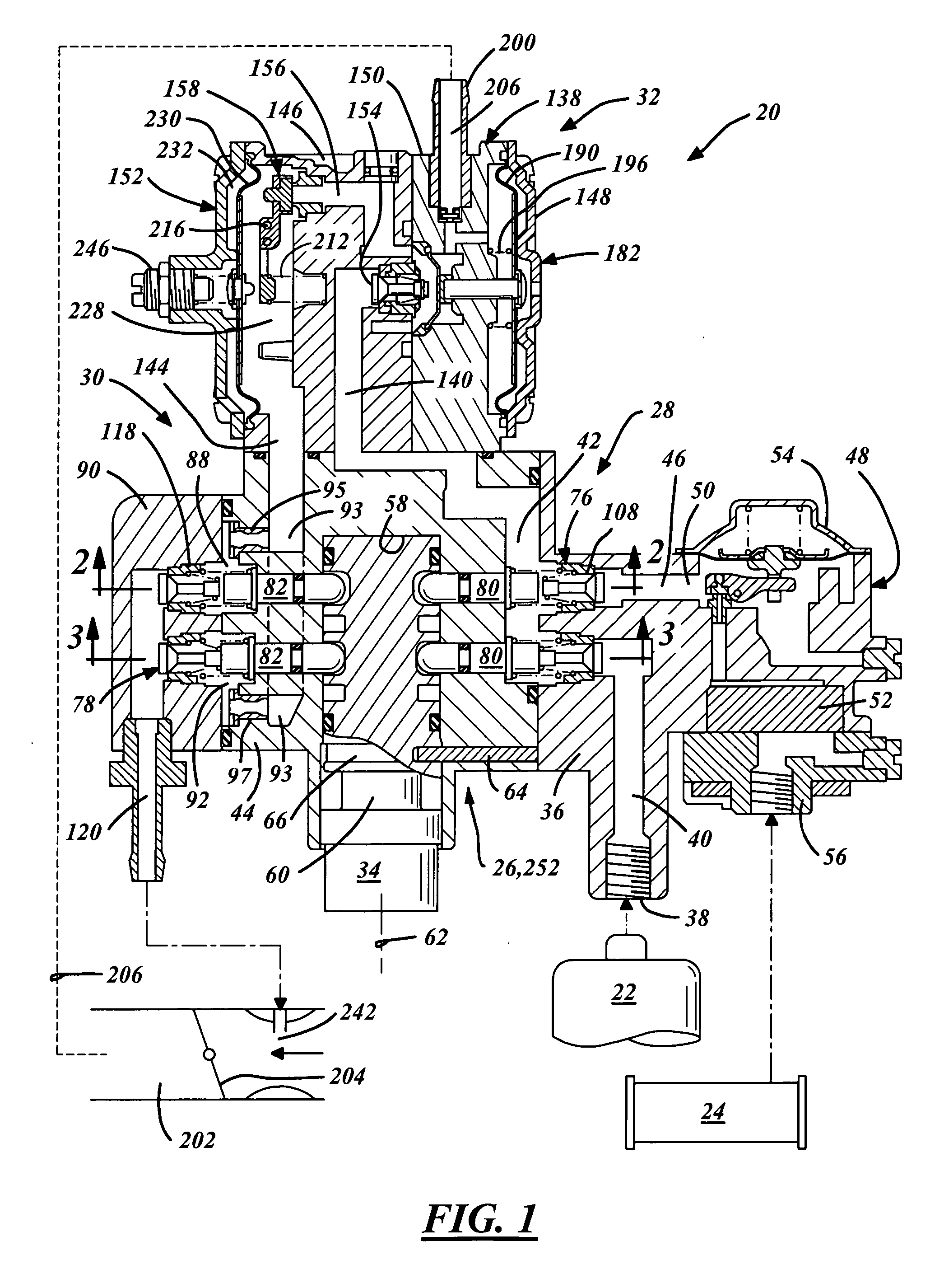
[0022] As best illustrated in FIG. 1, a fuel control device 20 supplies any selected one of a plurality of preferably petroleum-based fuels to a multi-fuel compatible combustion engine. As illustrated, the number of different fuels are preferably two (although more than two may be used) which are preferably butane and propane, which may be stored in a pressurized liquid state and expand into a gaseous state generally when flowing into the device 20 from a propane storage cylinder or source 22 and a butane storage cylinder or source 24. Although the multiple gaseous fuels are illustrated as propane and butane gas, the present invention is not limited to this example and may be adapted to handle any number or variety of gaseous fuels including but not limited to natural gas.

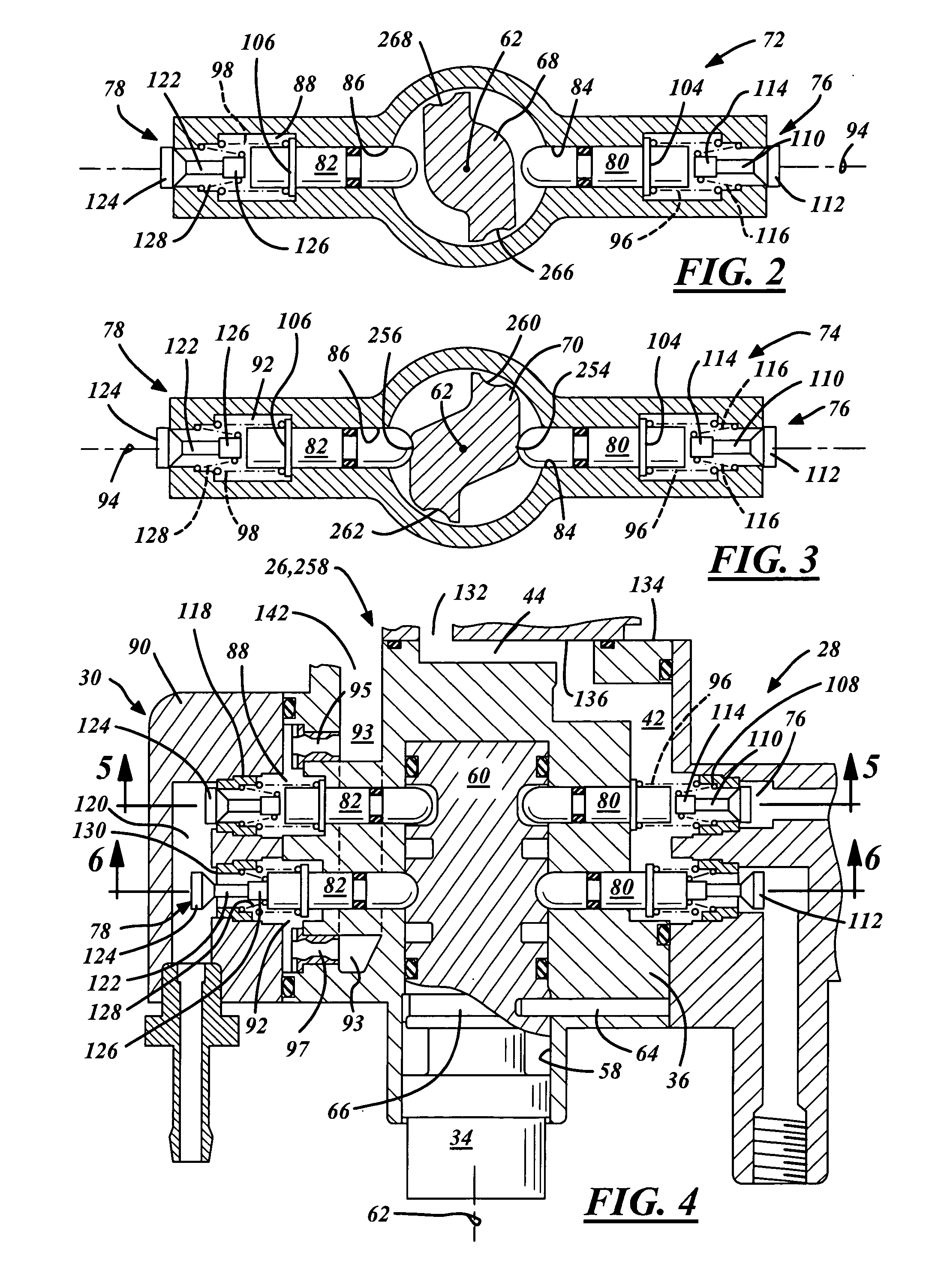
[0023] The fuel control device 20 is generally modularized, having a centralized fuel selection module 26 located between an inlet valve bank 28 and an interacting outlet valve bank 30. A fuel metering apparatus 3...


PUM

PropertyMeasurementUnit
inner diameteraaaaaaaaaa
pressureaaaaaaaaaa
timeaaaaaaaaaa

Abstract

A fuel control device for a combustion engine capable of running on any one of a plurality of fuels has a fuel selection module with a plurality of fuel type settings for selecting a specific fuel type whereupon the fuel control device controls the outlet pressure of the chosen fuel to a desired fuel pressure corresponding to the calorific properties of the chosen fuel. The fuel selection module preferably operates a plurality of fuel flow circuits each designated for a specific fuel type, and each having a biased closed inlet valve and a biased closed outlet valve. Located preferably between each inlet and outlet valve is a pressure regulator designated for the specific fuel type and controlling the outlet fuel pressure. The device preferably includes a fuel metering apparatus and a shutoff valve that communicate with, and control in part, fuel flow through the fuel flow circuits.

Description

RELATED APPLICATIONS [0001] Applicants claim priority of Japanese Application No. 2005-123595, filed on Apr. 21, 2005, and Japanese Application No. 2005-152777, filed on May 25, 2005. FIELD OF THE INVENTION [0002] The present invention relates to a fuel system and more particularly to a fuel control device for a combustion engine. BACKGROUND OF THE INVENTION [0003] Internal combustion engines can operate on multiple types of gaseous fuels such as petroleum-based propane gas and butane gas. Unfortunately, propane gas and butane gas have different calorific values and therefore must be provided to the engine at specific pre-determined pressures dependent upon the type of gas. Because specific gasses must flow at specific pressures the ability of an engine to run utilizing a variety of different fuels is somewhat moot because an easy and economical means of varying fuel supply pressures to correspond to different gas types is not available. SUMMARY OF THE INVENTION [0004] A fuel contro...

Claims


Application Information

Patent Timeline
Patent Type & Authority Applications(United States)
IPC IPC(8): F02M21/04B01F23/10
CPCF02M21/0215F02M21/0236F02D19/0642Y02T10/36Y02T10/32F02M21/0239Y02T10/30
Inventor FUJISAWA, KAZUHITOIKEDA, HIRONARIHORIKAWA, TAKASHI
Owner WALBRO ENGINE MANAGEMENT
Why Eureka
Try Eureka