
Image capture device
a technology of image capture and camera, which is applied in the direction of counting objects on conveyors, instruments, television systems, etc., can solve the problems of difficult assembly, limited incorporation in other equipment, and the device cannot be easily made compa
- Summary
- Abstract
- Description
- Claims
- Application Information
AI Technical Summary
Benefits of technology
Problems solved by technology
Method used
Image

Examples
Embodiment Construction
[0048]Below, embodiments of the invention are explained in the order of the configuration of an image capture device, an illumination mechanism, a hood configuration, and other embodiments.
[0049]Image Capture Device
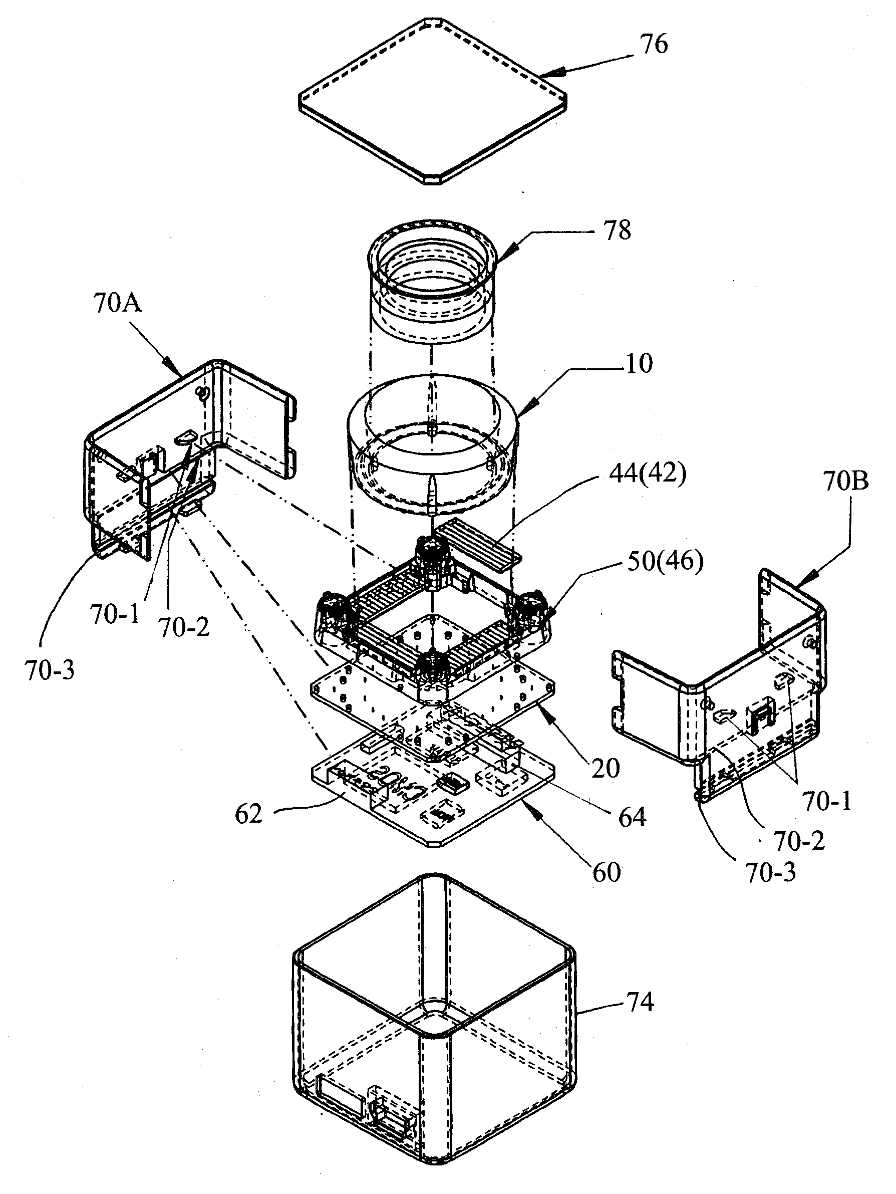
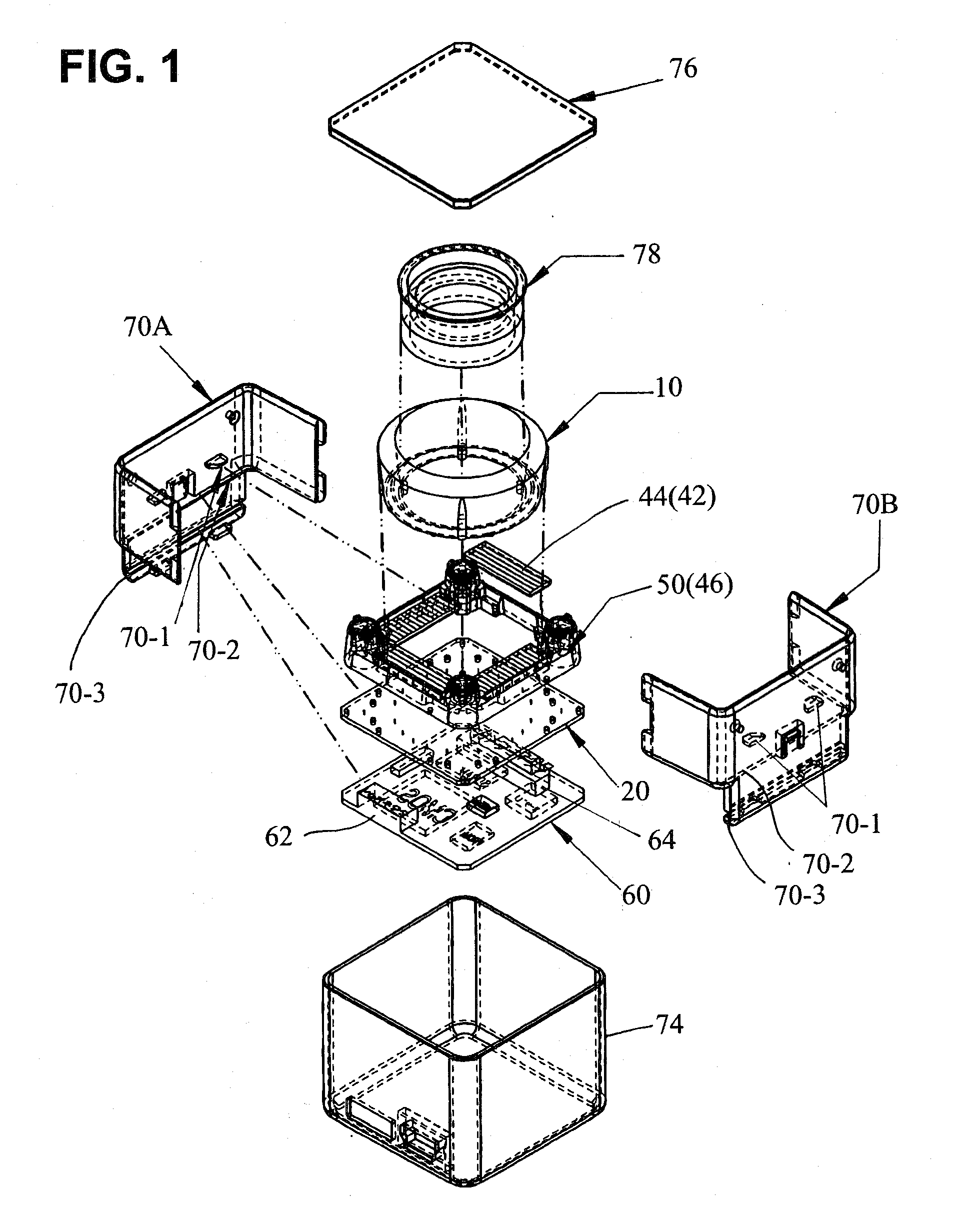
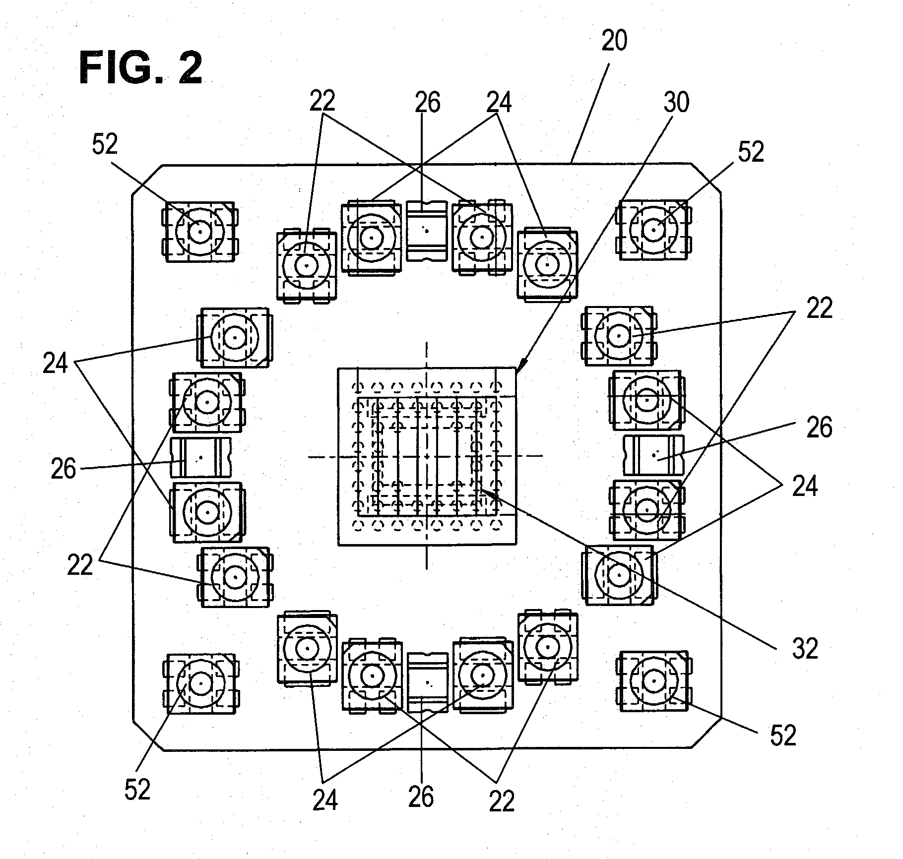
[0050]FIG. 1 is an exploded configuration diagram of the image capture device of one embodiment of the invention, FIG. 2 is a top view of the board in FIG. 1, and FIG. 3 is a cross-sectional view of the image capture device of FIG. 1.
[0051]As shown in FIG. 1, a camera board 20 and control board 60 are provided. As shown in FIG. 2, a CMOS image sensor or other image sensor 30 and a polarizing plate 32 are provided at the center of the camera board 20. On the periphery of the image sensor 30 on the camera board 20 are mounted a plurality of light-emitting elements 22, 24 and a plurality of light-receiving elements 26.
[0052]That is, an image sensor 30 is mounted at the center of the camera board 20, and a polarizing plate 32 is affixed thereupon. A plurality of light-emittin...
PUM
 Abstract
Description
Claims
Application Information