
Eureka
For R&D, Eureka makes reading and utilizing patents & technical documents easy.
Eureka AIR
Designed for self-driven R&D workflows. Generate viable solutions, solve complex R&D challenges, empower your innovation with AI.

Eureka Materials
Designed for material experts only. Revolutionize your material R&D, from search, analyze, to developing new materials.

TechResearch
Generate reliable direction feasibility study reports for your R&D in just a few steps.

TechSeek
Discover and master advanced knowledge NOW. Basics, ideas, possibilities, all at once.

TechMind
As an expert in R&D Theories, TechMind can generates customized viable solutions instantly.

TechRisk
Analyze your overall solution with one click, know your potential R&D risks in advance.

TechMonitor
Get weekly tech updates, stay abreast of the latest tech innovations and key insights.
Rotating pedestal with lock
- Summary
- Abstract
- Description
- Claims
- Application Information
AI Technical Summary
Problems solved by technology
Method used
Image

Examples
Embodiment Construction
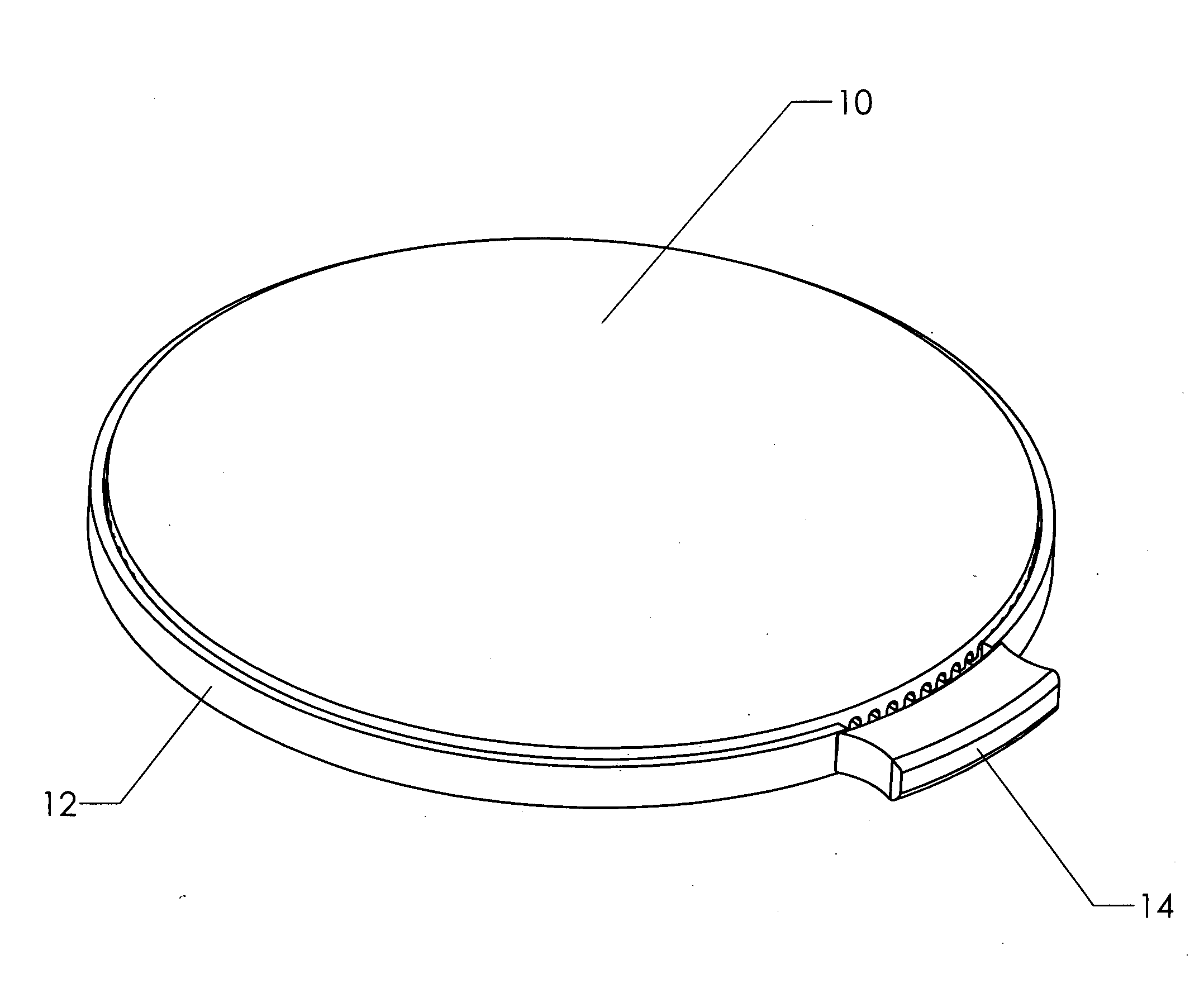
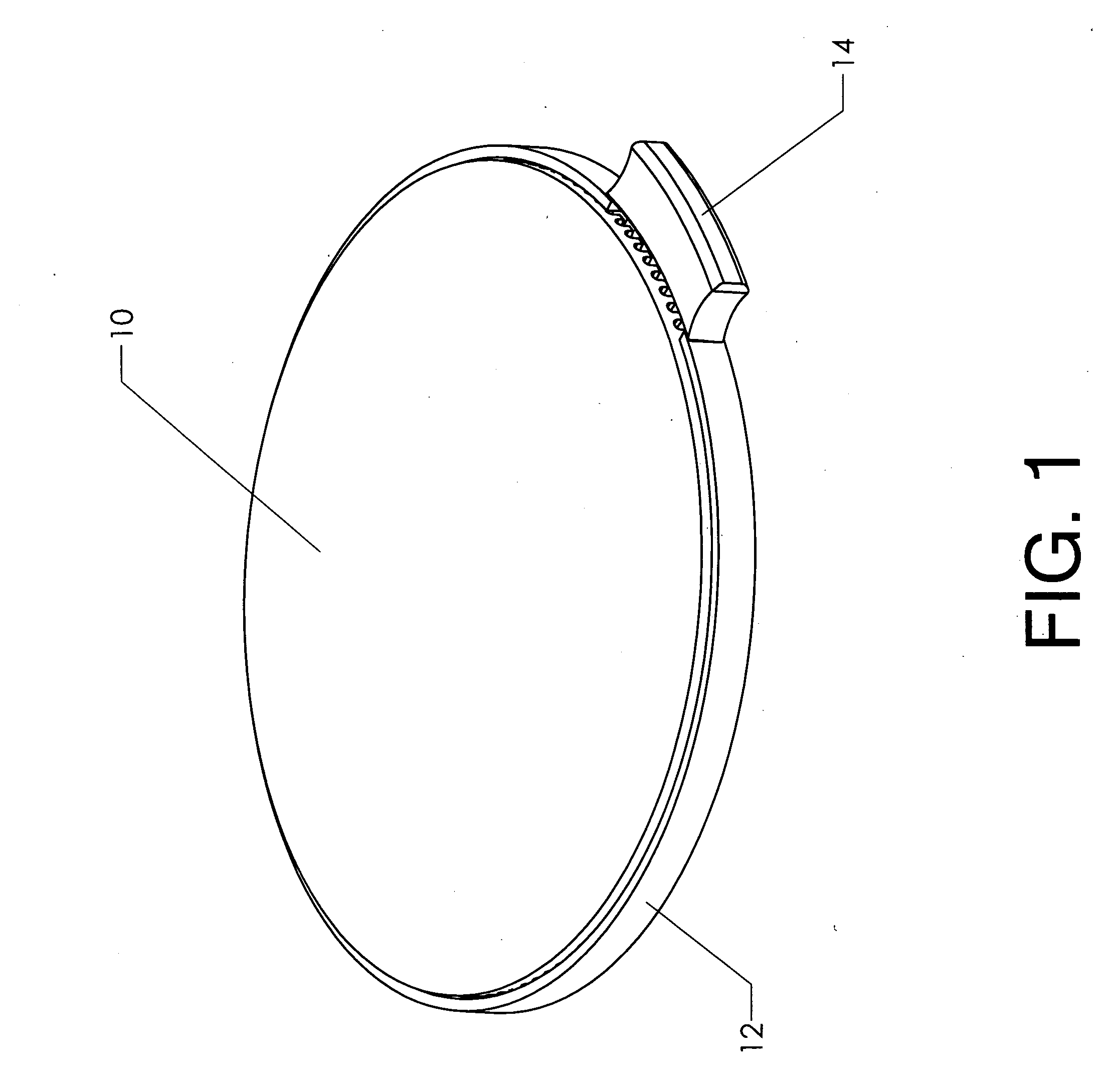
[0019]FIG. 1 shows the invention in an assembled state. Outer casing 12 is placed on any reasonably flat surface—such as a table or disk. Top 10 is rotatably connected to outer casing 12. It is normally free to rotate. Thus, an item placed on top 10 can be freely rotated to any desired orientation.
[0020]Top 10 is preferably covered in a relatively soft, heat-resistant material. Exemplary materials include rubber, neoprene, and many types of elastic polymer. The covering can be attached by any suitable method, including bonding or overmolding.
[0021]Lock 14 is shown in its disengaged position. The user engages the lock by pulling it outward, away from the center of the outer casing. When the lock is pulled outward, it locks the top in a fixed angular position with respect to the outer casing. Further rotation is thereby prevented until the lock is released.
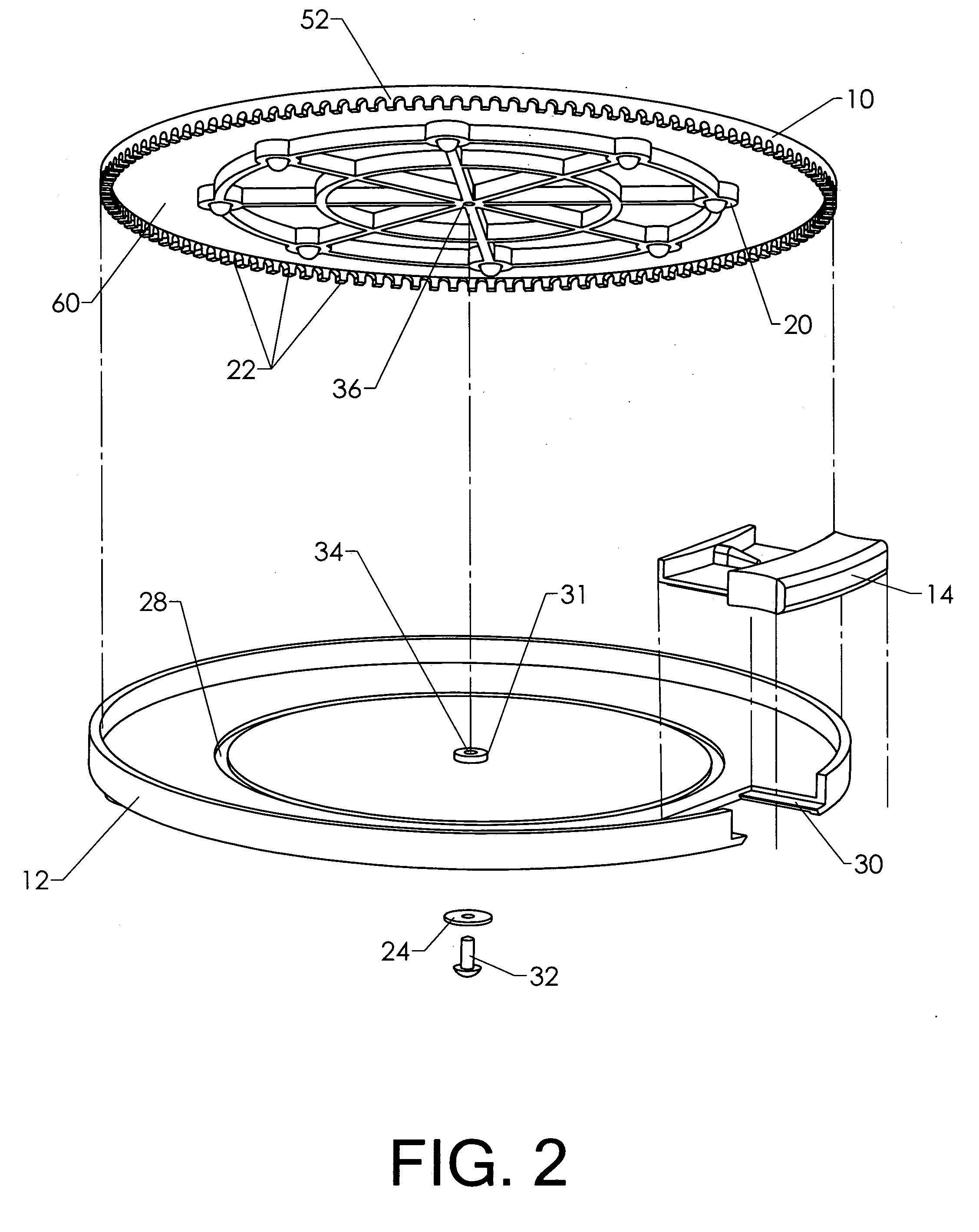
[0022]FIG. 2 shows the same device in an exploded state. The desired functionality could be accomplished using any number of inter...
PUM
 Abstract
Description
Claims
Application Information
 - R&D Engineer
- R&D Manager
- IP Professional
- Industry Leading Data Capabilities
- Powerful AI technology
- Patent DNA Extraction
Browse by: Latest US Patents, China's latest patents, Technical Efficacy Thesaurus, Application Domain, Technology Topic, Popular Technical Reports.
© 2024 PatSnap. All rights reserved.Legal|Privacy policy|Modern Slavery Act Transparency Statement|Sitemap|About US| Contact US: help@patsnap.com