
Planting pots and multi-compartment tray having self-orienting configuration

a multi-compartment tray and planter technology, applied in the field of planter pots and multi-compartment tray, can solve the problems of existing pots that require manual adjustment to properly orient, and cannot be automatically aligned and oriented

Inactive Publication Date: 2008-11-13
SMITH & WESSON +1
View PDF82 Cites 10 Cited by
  • Summary
  • Abstract
  • Description
  • Claims
  • Application Information

AI Technical Summary

Benefits of technology

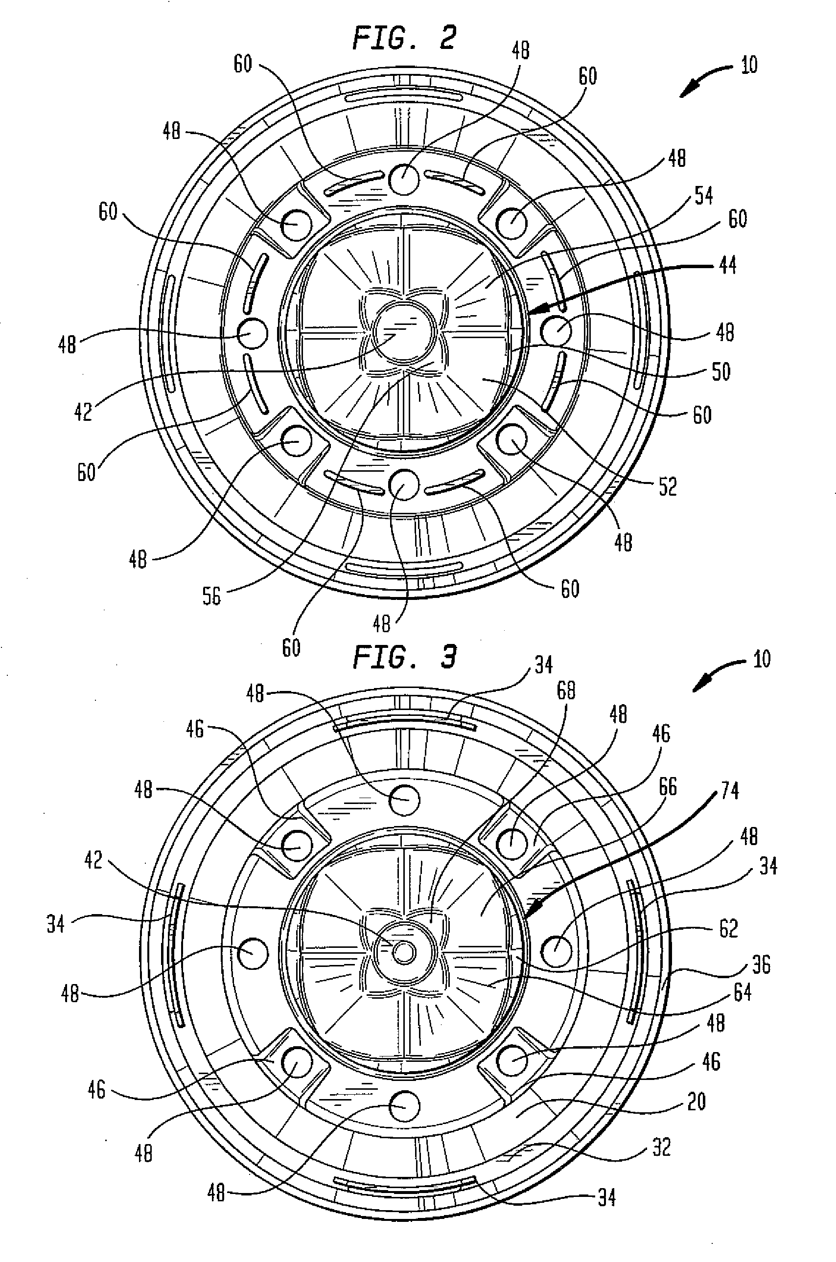
[0010]A multi-compartment tray is provided for holding a plurality of planting pots. Each compartment of the tray includes an upper portion, a bottom portion, and a compartment wall therebetween. The bottom portion of each compartment includes a plurality of alignment protrusions disposed radially about a central portion. The alignment protrusions include angled surfaces that co-act with the angled surfaces of the alignment recesses of the pot to urge the pot into a desired orientation when the pot is placed in the compartment. A plurality of bevels located near the upper portion provide room for allowing insertion of the optional identification tags into the slots of the pots when the pots are positioned in the tray.

Problems solved by technology

A particular problem with existing planting pots, and trays used therewith, is that the pots are not capable of being automatically aligned and oriented when placed in trays.
Moreover, even if identification tags are not used with the pots, existing pots require manual adjustment to properly orient the pots within the storage compartments of trays.

Method used


Image

  • Planting pots and multi-compartment tray having self-orienting configuration
  • Planting pots and multi-compartment tray having self-orienting configuration
  • Planting pots and multi-compartment tray having self-orienting configuration

Examples


Embodiment Construction

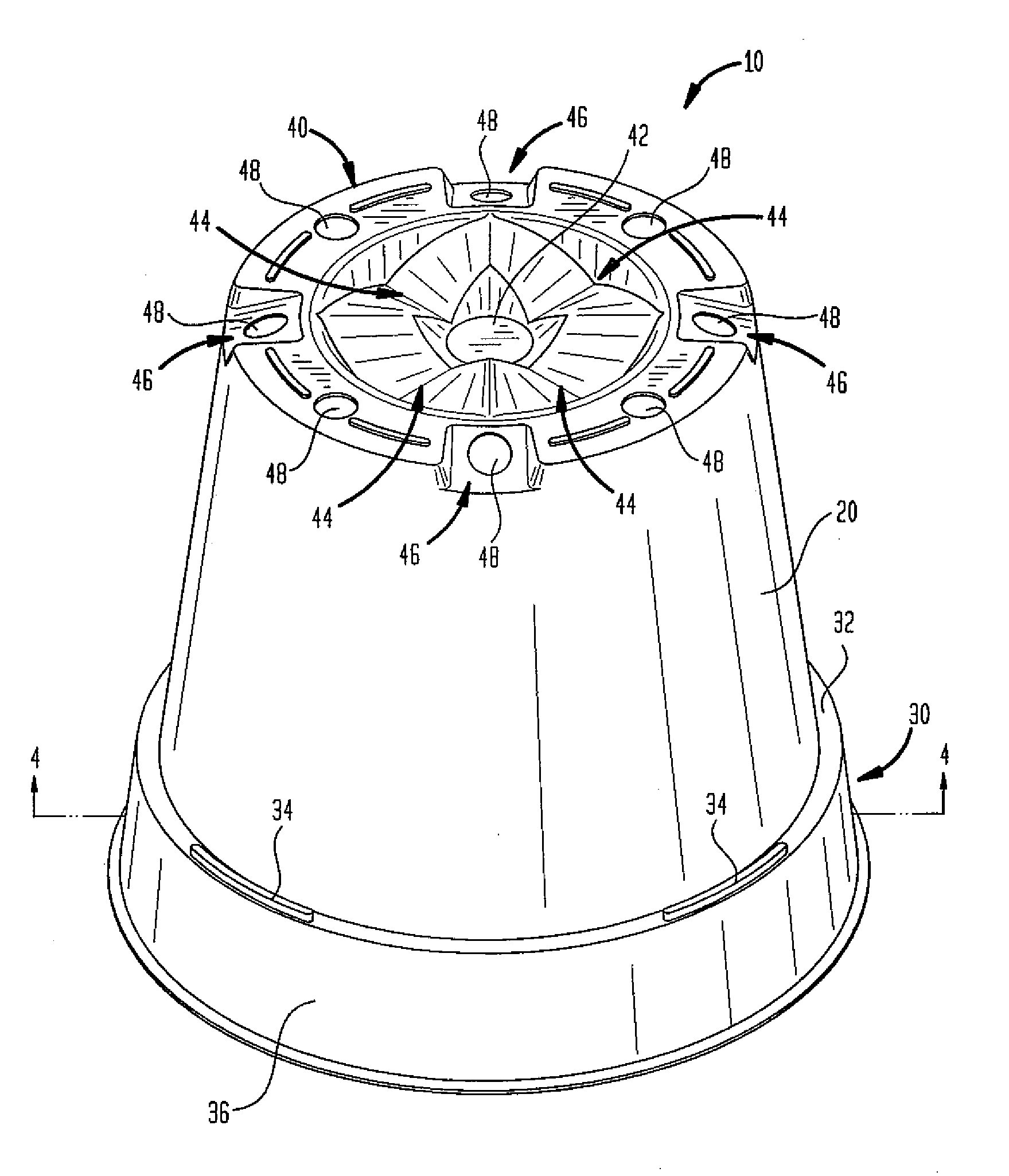
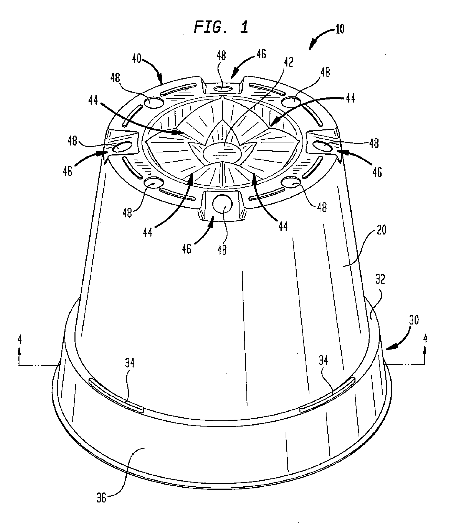
[0022]The present invention relates to planting pots and a multi-compartment tray, each having a self-orienting configuration for urging the pots into proper alignment when same are placed within the compartments of the tray. The planting pots include angled recesses disposed radially about the bottom portion of the pots. The compartments of the tray include angled protrusions disposed radially about the bottom portion of the compartment. The angled recesses of the pot engage with the angled protrusions of the compartment when the pot is placed in the compartment to urge the pot into proper alignment. One or more slots may be included along an upper portion of each pot for allowing optional identification tags to be inserted thereinto. The identification tags, if included, are positioned by the self-orienting configuration of the pots and tray to face in a desired direction.

[0023]Referring now to the drawings, FIG. 1 is an isometric view of a planting pot, generally indicated at 10,...


PUM


Abstract

Planting pots and a multi-compartment tray are provided, the pots and tray having a self-orienting configuration for urging the pots into proper alignment when same are placed within compartments of the tray. The pots include angled recesses disposed radially about the bottom portion of the pots. The compartments of the tray include angled protrusions disposed radially about the bottom portion of the compartment. The angled recesses of the pot engage with the angled protrusions of the compartment when the pot is placed in the compartment to urge the pot into proper alignment. A plurality of slots are included along an upper portion of each pot for allowing optional identification tags to be inserted thereinto. The identification tags, in addition to logos, artwork, or other indicia, if included, are positioned by the self-orienting configuration of the pots and tray to face in a desired direction.

Description

RELATED APPLICATIONS[0001]This application is a continuation of U.S. patent application Ser. No. 10 / 423,476, filed Apr. 25, 2003, now U.S. patent Ser. No. ______, the entire disclosure of which is expressly incorporated herein by reference.BACKGROUND OF THE INVENTION[0002]1. Field of the Invention[0003]The present invention relates to planting pots and a multi-compartment tray for holding same. More specifically, the present invention relates to planting pots and a multi-compartment tray having matching self-orienting configurations for aligning and locking the pots into position in the tray and for automatically orienting tags and other indicia in a uniform direction.[0004]2. Related Art[0005]Planting pots come in a variety of designs and configurations. Such pots are frequently used to plant flowers, vines, small shrubbery, and other types of plants. Often, planting pots include apertures located on the bottom portion thereof to allow drainage of water from soil packed into the po...

Claims


Application Information

Patent Timeline
IPC IPC(8): A01G9/02A01G9/10
CPCA01G9/02A01G9/021A01G9/04A01G9/104A01G9/045A01G9/006
Inventor SMITHHUNTINGTON, HENRY L.
Owner SMITH & WESSON
Learn More