Traction-drive type driving-force transmission mechanism and image forming apparatus equipped therewith

a transmission mechanism and driving force technology, applied in the direction of electrographic process, instruments, gearing, etc., can solve the problem of even wear on the outer peripheral surface of the sun roller

Active Publication Date: 2008-11-13
KYOCERA DOCUMENT SOLUTIONS INC
View PDF10 Cites 28 Cited by
  • Summary
  • Abstract
  • Description
  • Claims
  • Application Information

AI Technical Summary

Benefits of technology

[0008]It is an object of the present invention to provide a technique capable of generating an axially even traction force between the planetary roller and the sun roller.

Problems solved by technology

In this case, a pressure distribution on the inner peripheral surface of the planetary roller becomes uneven in an axial direction of the planetary roller, i.e., so-called “edge contact” occurs, to cause uneven wear on the outer peripheral surface of the sun roller.

Method used


Image

  • Traction-drive type driving-force transmission mechanism and image forming apparatus equipped therewith
  • Traction-drive type driving-force transmission mechanism and image forming apparatus equipped therewith
  • Traction-drive type driving-force transmission mechanism and image forming apparatus equipped therewith

Examples


Embodiment Construction

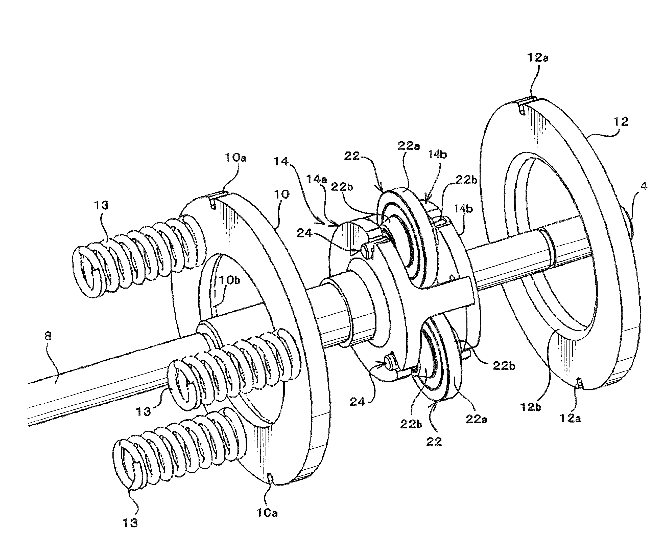
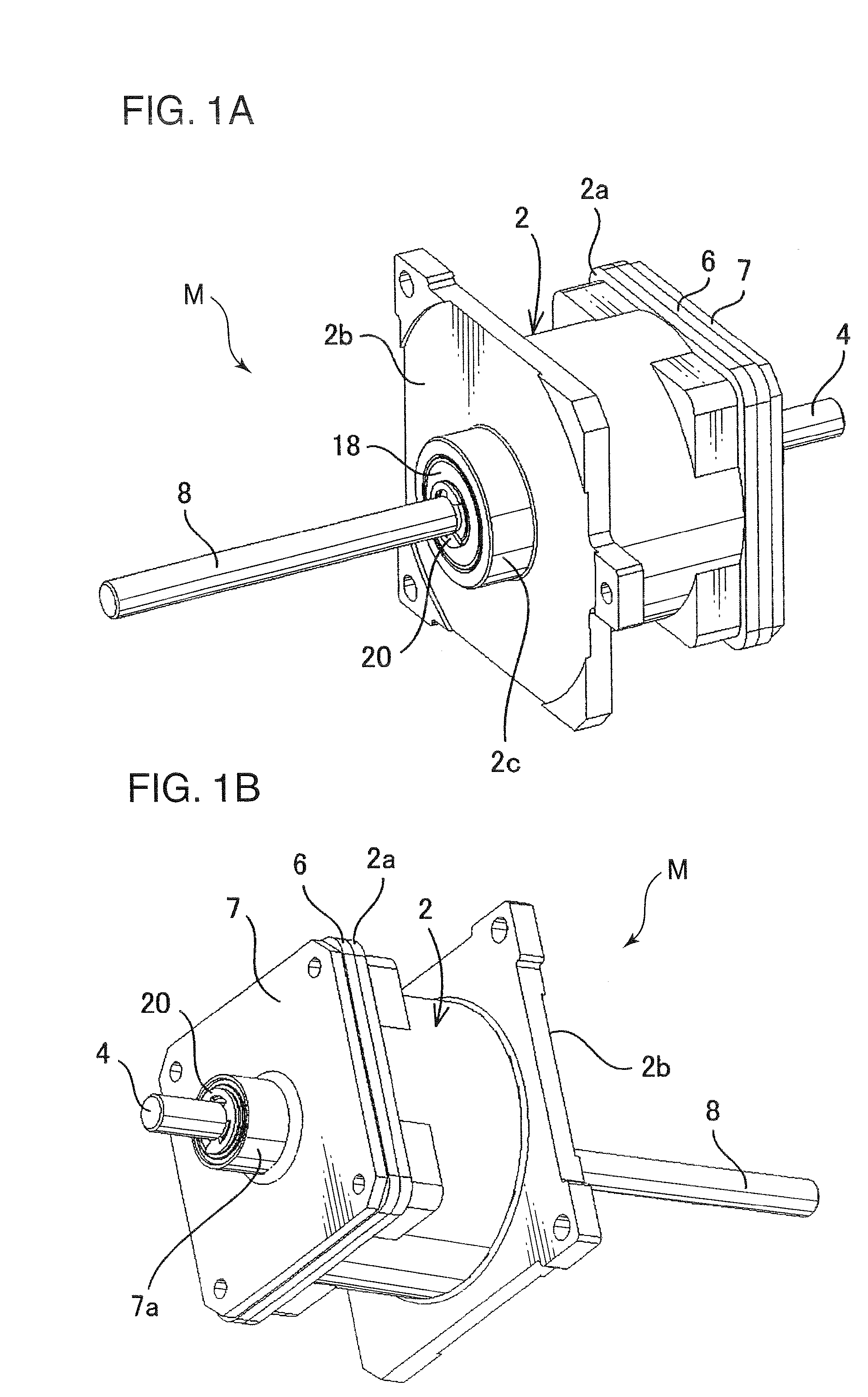
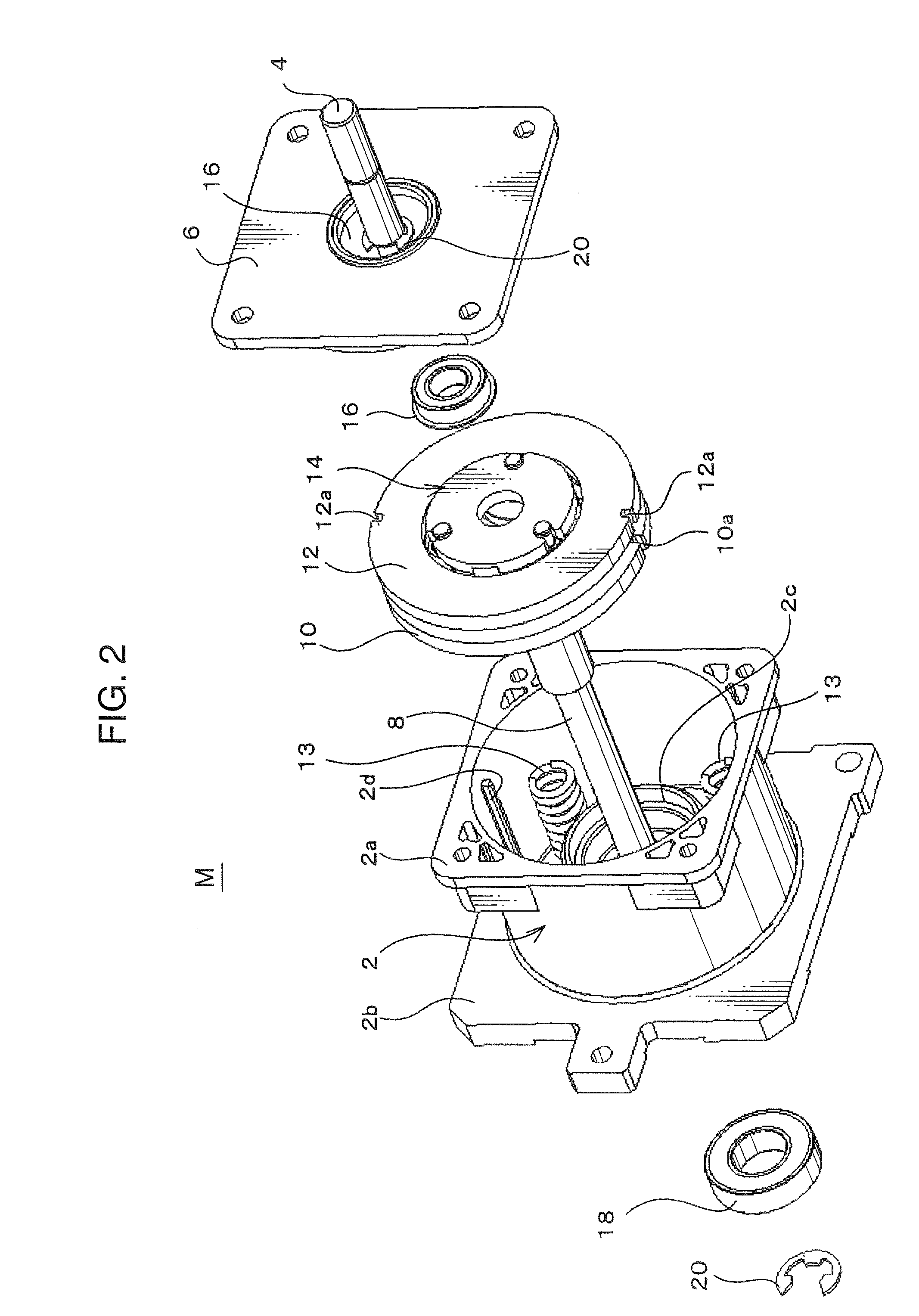
[0022]With reference to the drawings, the present invention will be specifically described based on an embodiment thereof. FIGS. 1A and 1B are perspective views showing an external appearance of a traction-drive type driving-force transmission mechanism M according to one embodiment of the present invention, when viewed from two different directions. The traction-drive type driving-force transmission mechanism M includes a cylindrical-shaped casing 2, a sun roller 4, an end plate 6, a bearing plate 7, and an output shaft 8.

[0023]The casing 2 has a rectangular-shaped flange 2a formed at one end thereof, and the flange 2a is formed with an opening which is closed by the end plate 6 having a shape corresponding to that of the flange 2a. The casing 2 further has a rectangular-shaped flange 2b formed at the other end on an opposite side of the flange 2a. The traction-drive type driving-force transmission mechanism M is adapted to be connected to a driving source, such as a motor (not sho...


PUM


Abstract

A traction-drive type driving-force transmission mechanism includes a sun roller having a first central axis about which the sun roller is rotatable. Shafts are provided and each has a second central axis aligned parallel to the first central axis. Planetary rollers are arranged rotatably along an outer peripheral surface of the sun roller and are supported respectively by the shafts. A guide member guides each shaft displaceably in a radial direction of the sun roller while maintaining the parallel relationship between the first and second central axes. A pressing member presses each planetary roller against the outer peripheral surface of the sun roller so that a driving force can be transmitted by a traction force between the sun roller and each of the planetary rollers.

Description

BACKGROUND OF THE INVENTION[0001]1. Field of the Invention[0002]The present invention relates to a traction-drive type driving-force transmission mechanism capable of transmitting a driving force or reducing a rotational speed, through means of a traction force generated between rollers, and an image forming apparatus equipped with the traction-drive type driving-force transmission mechanism.[0003]2. Description of the Related Art[0004]As a prior art relating to traction-drive type driving-force transmission mechanisms, there has been known a mechanism which comprises a sun roller coupled to a rotary shaft, a plurality of planetary rollers arranged around the sun roller, and a carrier supporting respective planetary shafts of the planetary rollers (see, for example, JP 2000-329206A, which will hereinafter be refereed to as “D1”). The mechanism disclosed in the D1 is designed such that each of the planetary rollers is rotated while being circulated outside the sun roller and along a ...

Claims


Application Information

Patent Timeline
Patent Type & Authority Applications(United States)
IPC IPC(8): F16H37/06G03G15/00F16H13/08
CPCF16H13/06G03G15/161Y10T74/19042G03G15/757G03G15/1615G03G15/5008
Inventor MARUMOTO, TAKESHI
Owner KYOCERA DOCUMENT SOLUTIONS INC
Why Eureka
Try Eureka