Imaging lens

Active Publication Date: 2008-11-27
TIANJIN OFILM OPTO ELECTRONICS CO LTD
View PDF5 Cites 8 Cited by
  • Summary
  • Abstract
  • Description
  • Claims
  • Application Information

AI Technical Summary

Benefits of technology

[0011]The invention has been made in view of the above circumstances and provides an imaging lens having high imaging performance, compact configuration and excellent manufacturing efficiency.

Problems solved by technology

However, the aspheric surfaces are disadvantageous in manufacturing efficiency, and the cost may increase.
However, those lenses do not achieve a certain level of compatibility between good imaging performance and desirable compactness.

Method used


Image

  • Imaging lens
  • Imaging lens
  • Imaging lens

Examples


example

[0109]Next, specific numerical examples of the imaging lens according to this embodiment will be described. First to eleventh numerical examples (Examples 1 to 11) will be collectively described below.

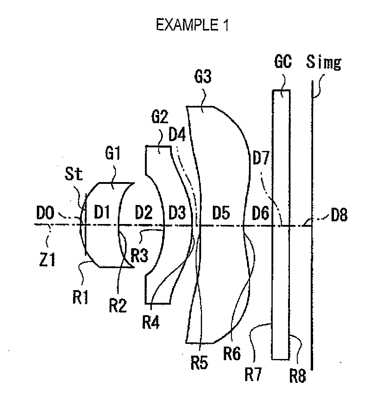
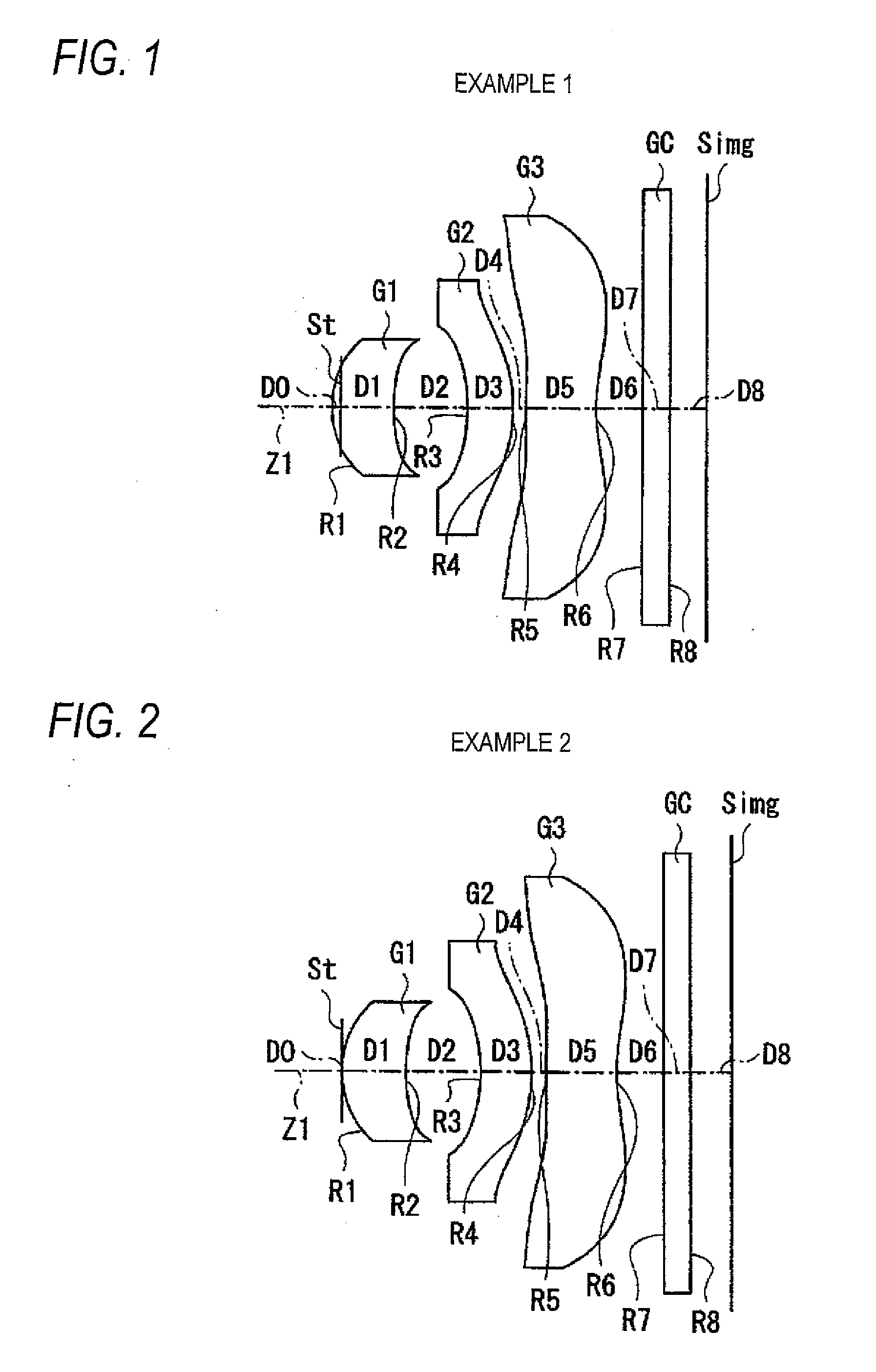
[0110]FIGS. 12 and 13 show specific lens data corresponding to the configuration of the imaging lens shown in FIG. 1. Particularly, the basic lens data is shown in FIG. 12 and data relating to aspheric surfaces is shown in FIG. 13. The surface number Si in the lens data shown in FIG. 12 denotes the number of an i-th surface (where i=1 to 9) when the aperture stop St is counted as the zeroth surface and the surface number sequentially increases toward the image side. The curvature radius Ri denotes a curvature radius (mm) of the i-th surface from the object side so as to correspond to reference numeral Ri shown in FIG. 1. The surface separation Di denotes a separation (mm) between the i-th surface Si from the object side and the (i+1)-th surface Si+1 from the object side on the optical ...


PUM


Abstract

An imaging lens includes, in order from an object side, a first lens having a positive refractive power and having a meniscus shape with a convex surface directed to the object side thereof, a second lens having a concave object-side surface and a third lens having a negative refractive power in a vicinity of an optical axis. Each of the second and third lenses has at least one aspheric surface. The following conditional expressions are satisfied:0.8<f1 / f<1.2   (1)11<|f2 / f|  (2)0.04<SA / Y<0.09   (3)TL / 2Y<0.9   (4)whereSA denotes the amount of sag of the object-side surface of the second lens in a position where a principal ray passes the maximum image height,Y denotes the maximum image height, andTL denotes a distance from an object-side surface of the first lens to an image formation position.

Description

CROSS-REFERENCE TO RELATED APPLICATIONS[0001]This application is based upon and claims the benefit of priority from the Japanese Patent Application No. 2007-93306 filed on Mar. 30, 2007; the entire contents of which are incorporated herein by reference.BACKGROUND OF THE INVENTION[0002]1. Technical Field[0003]The invention relates to a fixed-focus imaging lens that can be suitably mounted on a small-sized imaging apparatus such as (i) a digital camera using an imaging device such as a CCD (Charge Coupled Device) or a CMOS (Complementary Metal Oxide Semiconductor), (ii) a camera using a silver halide film, and the like.[0004]2. Description of the Related Art[0005]In recent years, as permeation of personal computers in homes or the like, a digital still camera (hereinafter, referred to as a “digital camera”) capable of inputting image information, such as photographed scenes, persons, or the like, to the personal computer have come into wide use rapidly. As cellular phones are sophisti...

Claims


Application Information

Patent Timeline
IPC IPC(8): G02B13/18
CPCG02B13/0035G02B13/16G02B13/18
Inventor SATO, KENICHITANIYAMA, MINORU
Owner TIANJIN OFILM OPTO ELECTRONICS CO LTD
Why Eureka
Try Eureka