Check patentability & draft patents in minutes with Patsnap Eureka AI!

Method of Encoding and Decoding Video Signals

Active Publication Date: 2008-11-27
LG ELECTRONICS INC
View PDF2 Cites 24 Cited by
  • Summary
  • Abstract
  • Description
  • Claims
  • Application Information

AI Technical Summary

Benefits of technology

[0021]Accordingly, the present invention has been made keeping in mind the above problems occurring in the prior art, and an object of the present invention is to provide a method of simply and efficiently up-sampling a base layer in interlayer prediction.

Problems solved by technology

In the case where the bit rate is low, image quality is significantly degraded.

Method used


Image

  • Method of Encoding and Decoding Video Signals
  • Method of Encoding and Decoding Video Signals
  • Method of Encoding and Decoding Video Signals

Examples


first embodiment

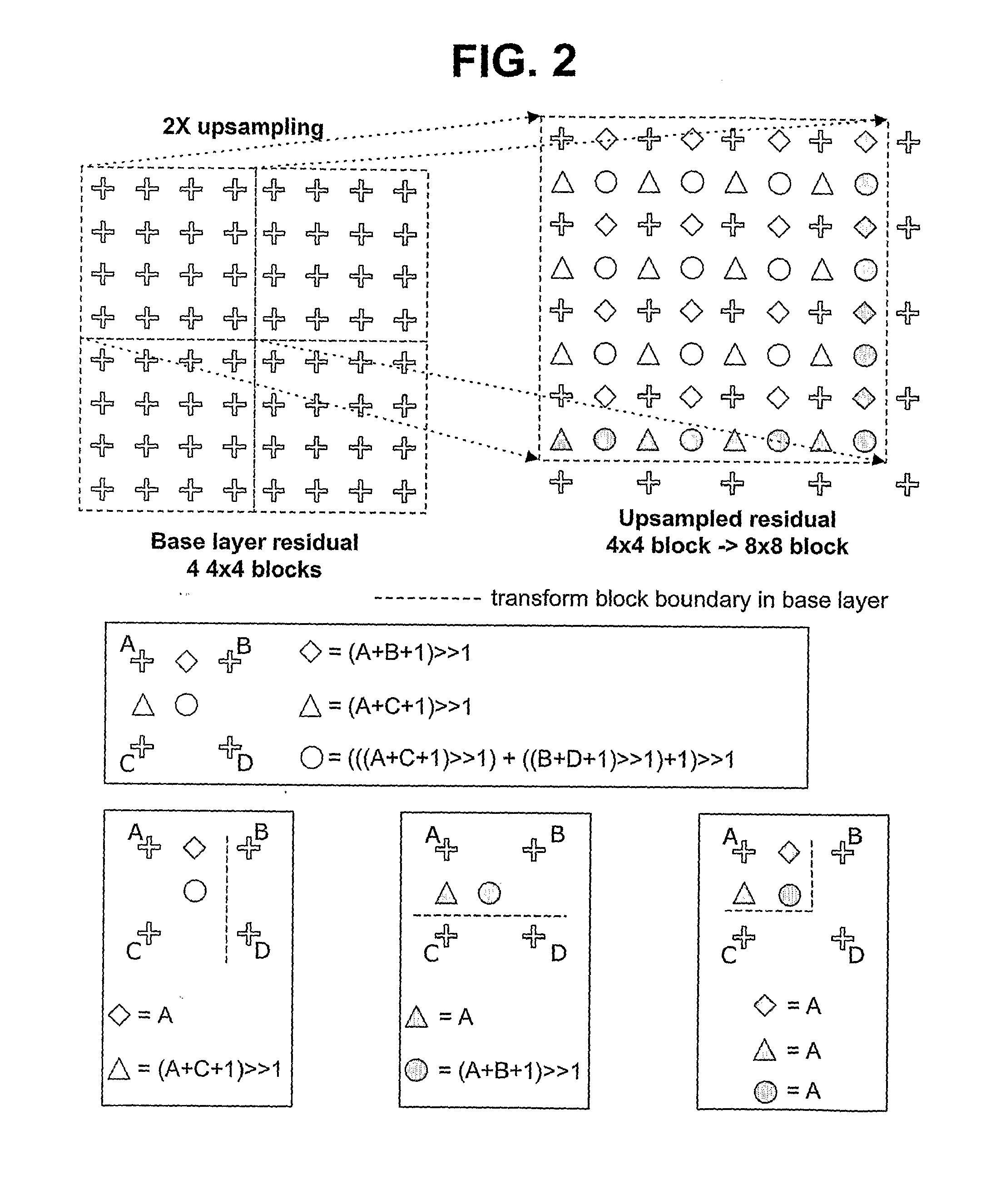
[0044]Accordingly, in the present invention, when residual up-sampling is performed, only the boundary for motion compensated prediction partitioning is taken into consideration, instead of the boundary of a transform block.

[0045]That is, as long as the boundary of a transform block is not the boundary for motion compensated prediction partitioning, filtering for up-sampling is applied beyond the boundary of the transform block. In this case, the boundary of a base layer, not that of an enhanced layer, is used as the boundary of the transform block and the boundary for the motion compensated prediction partitioning.

[0046]In MB0, with the boundaries of two upper 8×8 prediction blocks, the boundaries of two lower left 8×4 prediction blocks and the boundaries of two lower right 4×8 prediction blocks, instead of the boundary of a 4×4 transform block, being considered as the boundary of a block, different operations are applied to pixels existing at the boundary to perform residual up-sa...

second embodiment

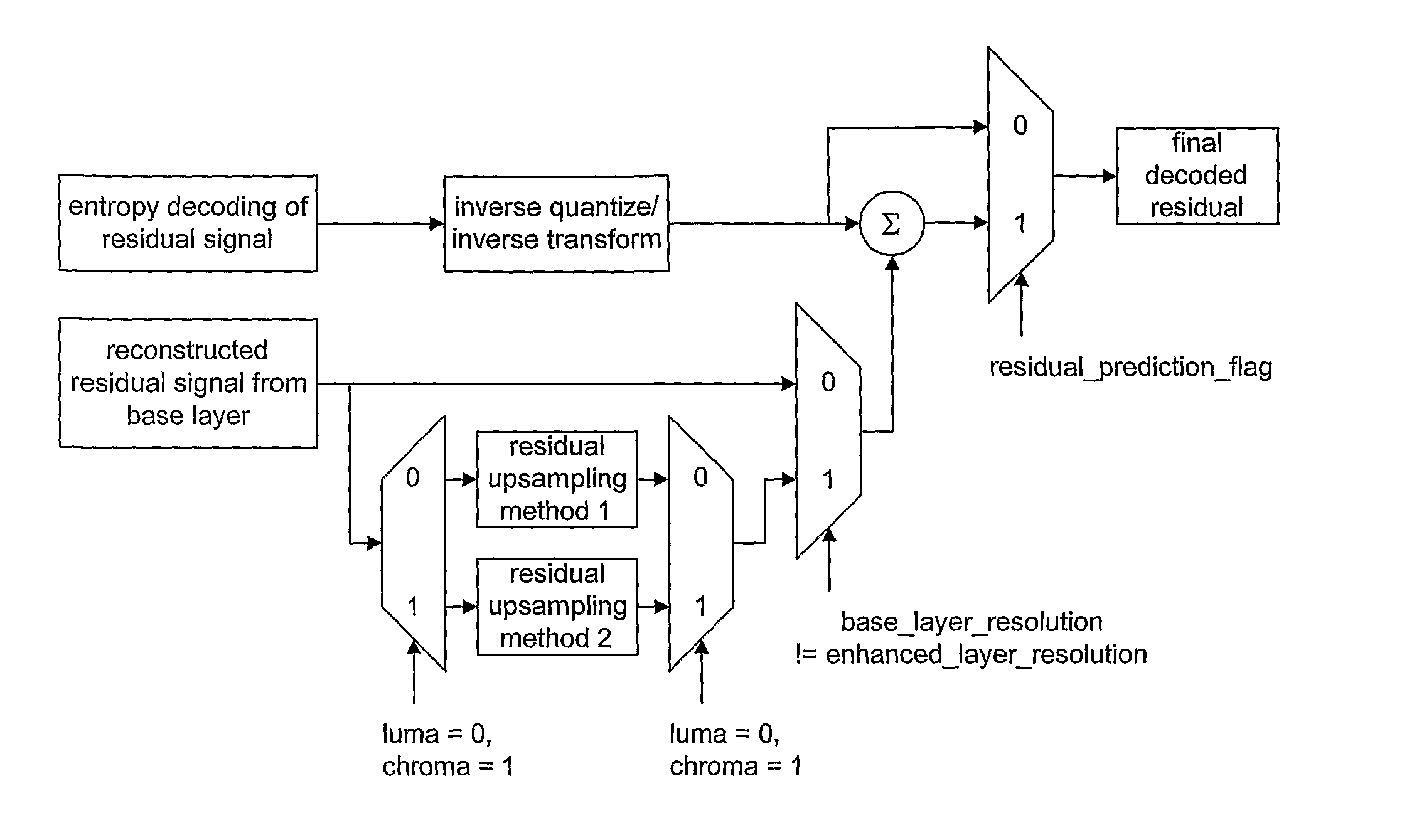
[0049]Accordingly, in the present invention, different up-sampling filters are applied to luminance signals and chrominance signals. An up-sampling filter simpler than that for luminance signals is applied to chrominance signals.

[0050]FIG. 5 illustrates a process of up-sampling the luminance and chrominance signals of a base layer, which has residual data, using different methods and decoding an enhanced layer, which has been encoded in an inter mode and has residual data, using up-sampling results, according to the second embodiment of the present invention.

[0051]FIG. 6 illustrates a process of up-sampling the luminance and chrominance signals of a base layer, which have decoded image data, using different methods and decoding an enhanced layer, which has been encoded in an intra base mode, using up-sampling results, according to the second embodiment of the present invention.

[0052]As illustrated in FIGS. 5 and 6, different filtering methods are applied to luminance and chrominance...


PUM


Abstract

Disclosed herein is a method of encoding video signals. The method includes creating a bit stream of a first layer by encoding the video signals, and creating a bit stream of a second layer by encoding the video signals based on the first layer. When residual data, corresponding to an image difference, within the first layer, is up-sampled and used for the encoding of the second layer, the residual data is up-sampled for each block that is predicted based on motion compensation.

Description

1. TECHNICAL FIELD[0001]The present invention relates to a method of encoding and decoding video signals.2. BACKGROUND ART[0002]A Scalable Video Codec (SVC) scheme is a video signal encoding scheme that encodes video signals at the highest image quality and can represent images at some level of image quality even though only part of a picture sequence (a sequence of frames that are intermittently selected from among the entire picture sequence) that is produced by the encoding is decoded and used.[0003]A picture sequence encoded using the scalable method allows images to be represented at some level of image quality even if only a partial sequence thereof is received and processed. In the case where the bit rate is low, image quality is significantly degraded. In order to overcome this problem, a separate auxiliary picture sequence for the low bit rate, for example, small screens and / or a picture sequence having a low frame rate, may be provided.[0004]An auxiliary picture sequence i...

Claims


Application Information

Patent Timeline
IPC IPC(8): H04N7/50
CPCH04N19/61H04N19/117H04N19/186H04N19/59H04N19/82H04N19/33H04N19/182H04N19/53H04N19/30
Inventor YOON, DOE HYUNPARK, JI HOPARK, SEUNG WOOKJEON, BYEONG MOONKIM, DONG SEOKUM, SOUNG HYUN
Owner LG ELECTRONICS INC
Features
  • R&D
  • Intellectual Property
  • Life Sciences
  • Materials
  • Tech Scout
  • Unparalleled Data Quality
  • Higher Quality Content
  • 60% Fewer Hallucinations
Learn More