Eureka AIR delivers breakthrough ideas for toughest innovation challenges, trusted by R&D personnel around the world.

Image forming apparatus

Inactive Publication Date: 2008-11-27
KONICA MINOLTA BUSINESS TECH INC
View PDF5 Cites 8 Cited by
  • Summary
  • Abstract
  • Description
  • Claims
  • Application Information

AI Technical Summary

Benefits of technology

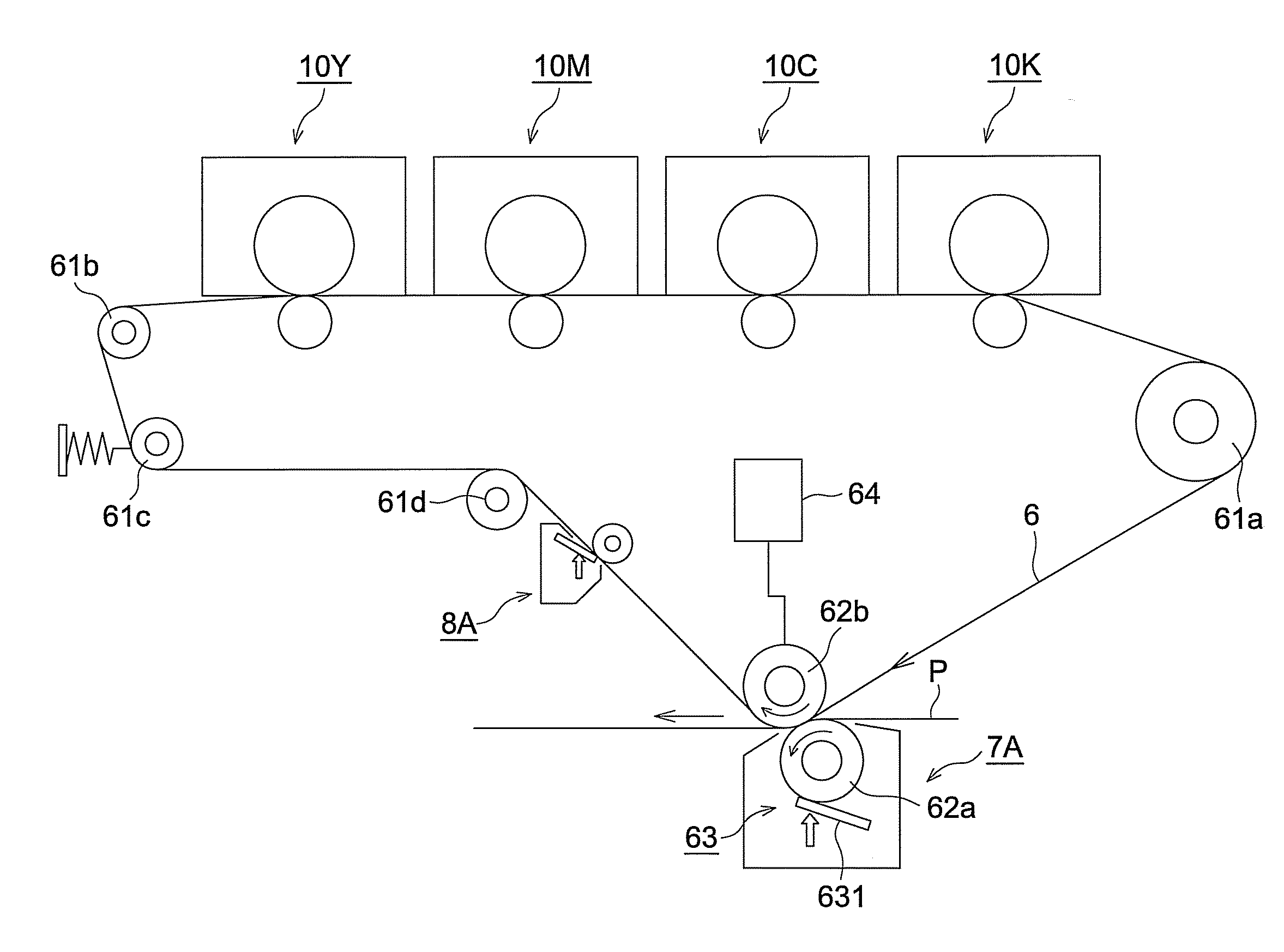
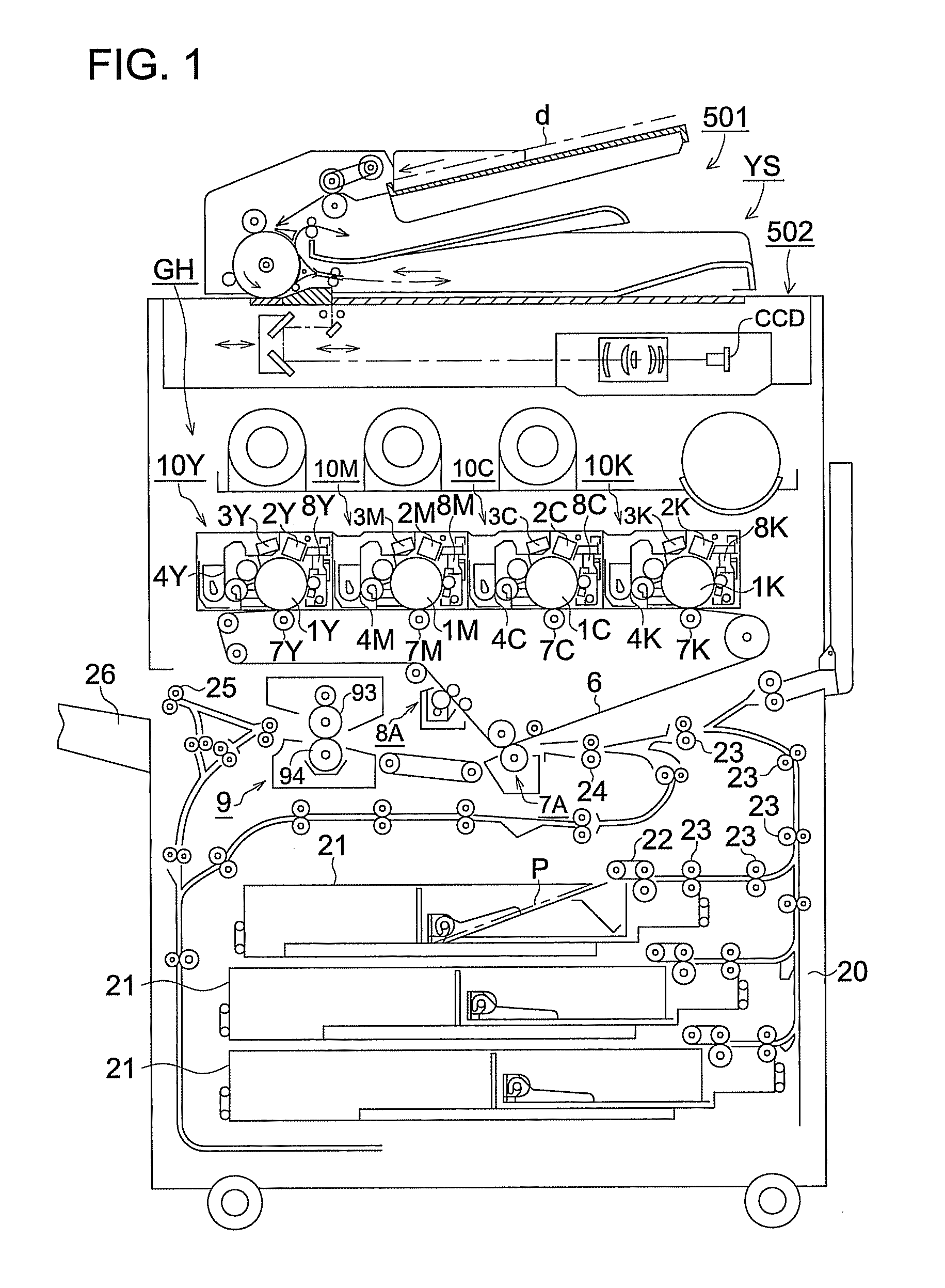
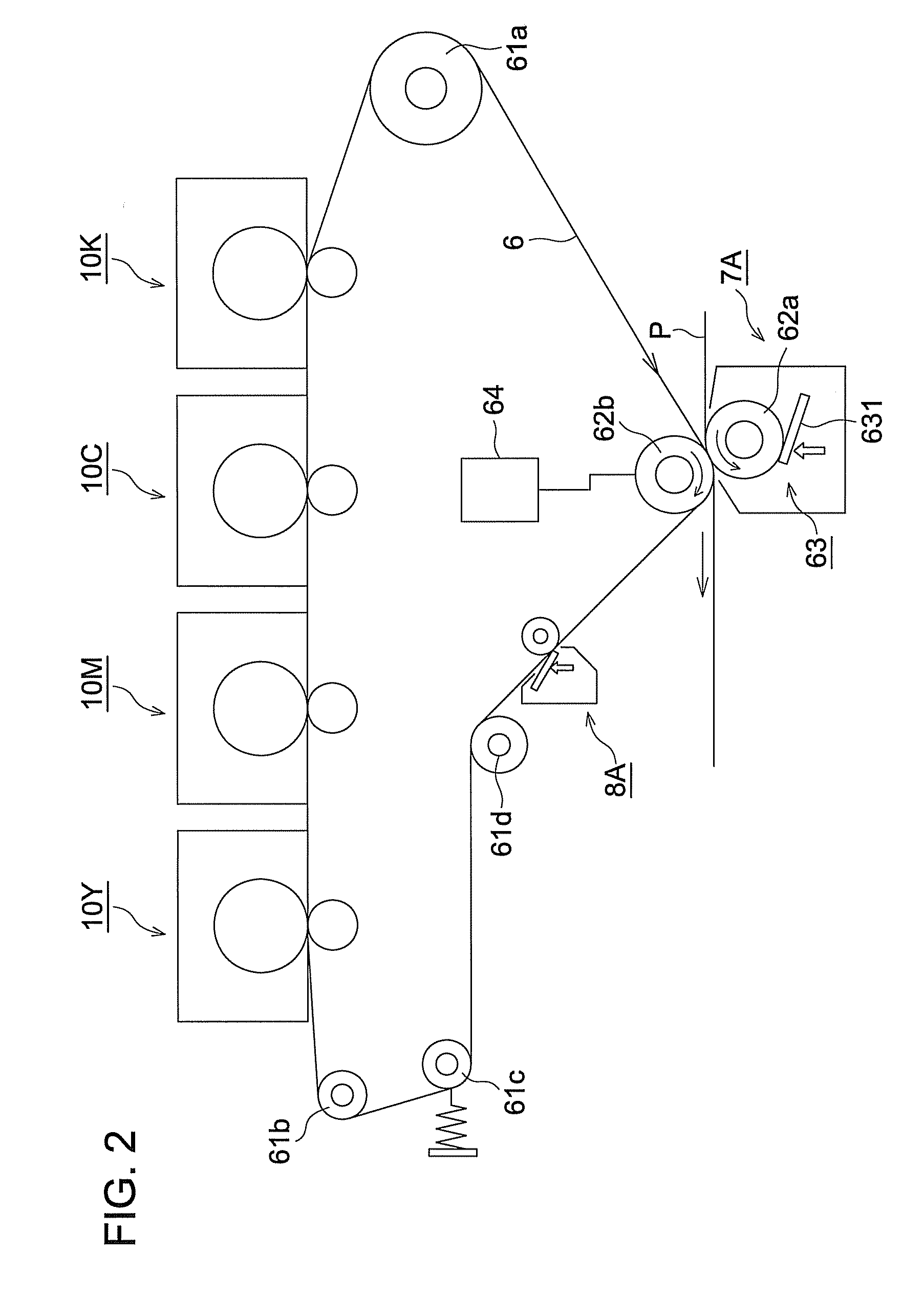
[0011]An object of the present invention is to provide an image forming apparatus that toner is not remain on the intermediate transfer member thereof, and the bending roller being in contact with the outer surface of the intermediate transfer member is not soiled with toner.

Problems solved by technology

However, in this method having the bending roller, if toner remains on the intermediate transfer member after transferring, the toner adheres on the bending rollers and begrimes inside the apparatus or the toner comes in contact with the intermediate transfer member and damages a surface of the intermediate transfer member.
Further, the damage mark is transferred onto the recording sheet and a problem that the printing quality is deteriorated occurs.
For the above problem, there is a case that in the cleaning method disclosed in the U.S. Pat. No. 3,805,782, transfer to the transfer roller or to the recording sheet cannot be performed completely.

Method used


Image

  • Image forming apparatus
  • Image forming apparatus
  • Image forming apparatus

Examples


embodiment

[0055]Next, table 1 shows a secondary transfer current value at a ordinary image transfer, a secondary transfer current value in the recovery sequence, number of prints when the intermediate transfer member cleaning device becomes out of order and number of prints when the bending roller is begrimed.

TABLE 1Secondary transfercurrentAt holtIntermediatewithouttransferAdhesion ofsheet / Atmembertoner on theAt imagerecovery duecleaningbendingtransferto jamfailurerollerEmbodiment 1−50 μA−120 μA No failureNo failureoccurred upoccurred upto 500kpto 500kpEmbodiment 2−50 μA−100 μA No failureNo failureoccurred upoccurred upto 500kpto 500kpEmbodiment 3−50 μA−60 μANo failureNo failureoccurred upoccurred upto 500kpto 500kpEmbodiment 4−50 μA−50 μAFailureNo failureoccurred atoccurred up420kpto 500kpEmbodiment 5−50 μA−40 μAFailureNo failureoccurred atoccurred up400kpto 500kp

Common Condition

[0056]Process speed: 220 mm / sec.

Intermediate Transfer Member Cleaning Conditions

[0057]Blade contact pressure: 18 ...


PUM


Abstract

In the recovery sequence after detecting recording medium conveyance jam or after detecting empty of recording medium in the sheet feeding tray, by applying a bias having the same polarity as that of the bias of the secondary transfer, remaining toner on the intermediate transfer member is transferred onto the secondary transfer roller side and a part of remaining toner not transferred by slipping through is cleaned by an intermediate member cleaning device disposed between the secondary transfer device and a bending roller being in contact with an outer surface of the intermediate transfer member.

Description

[0001]This application is based on Japanese Patent Application No. 2007-137596 filed on May 24, 2007, in Japanese Patent Office, the entire content of which is hereby incorporated by reference.BACKGROUND OF THE INVENTION[0002]The present invention relates to an image forming apparatus having an intermediate transfer member.[0003]In the past, an image forming method using an intermediate transfer device having an intermediate transfer member has been commonly known in a field of a copying machine, a printer and a facsimile machine using an electrophotographic method. In the method using the intermediate transfer device, by inserting one more transfer process into a process where a toner image is transferred from an image carrier (so called photoconductive member) to a recording media (so called recording sheet), after the toner image is primarily transferred from the photoconductive member to the intermediate transfer member, a primary transfer image on the intermediate transfer memb...

Claims


Application Information

Patent Timeline
IPC IPC(8): G03G15/00
CPCG03G15/161G03G15/5012G03G2215/0129G03G2215/1652G03G2215/1661
Inventor KABASHIMA, HIROTAKATANAKA, HIDEAKI
Owner KONICA MINOLTA BUSINESS TECH INC
Why Eureka
Eureka Blog
Learn More