
Hockey stick

a hockey stick and stick body technology, applied in the field of hockey sticks, can solve the problem that the blade cannot meet the requirement of hitting the puck by various skills, and achieve the effect of reducing the number of players

Inactive Publication Date: 2009-01-01
SHIU HSIU CHENG
View PDF9 Cites 25 Cited by
  • Summary
  • Abstract
  • Description
  • Claims
  • Application Information

AI Technical Summary

Problems solved by technology

However, the conventional hockey sticks have the entire blade with the same property so that the blade cannot meet the requirement of hitting the puck by various skills.

Method used


Image

  • Hockey stick
  • Hockey stick
  • Hockey stick

Examples


Embodiment Construction

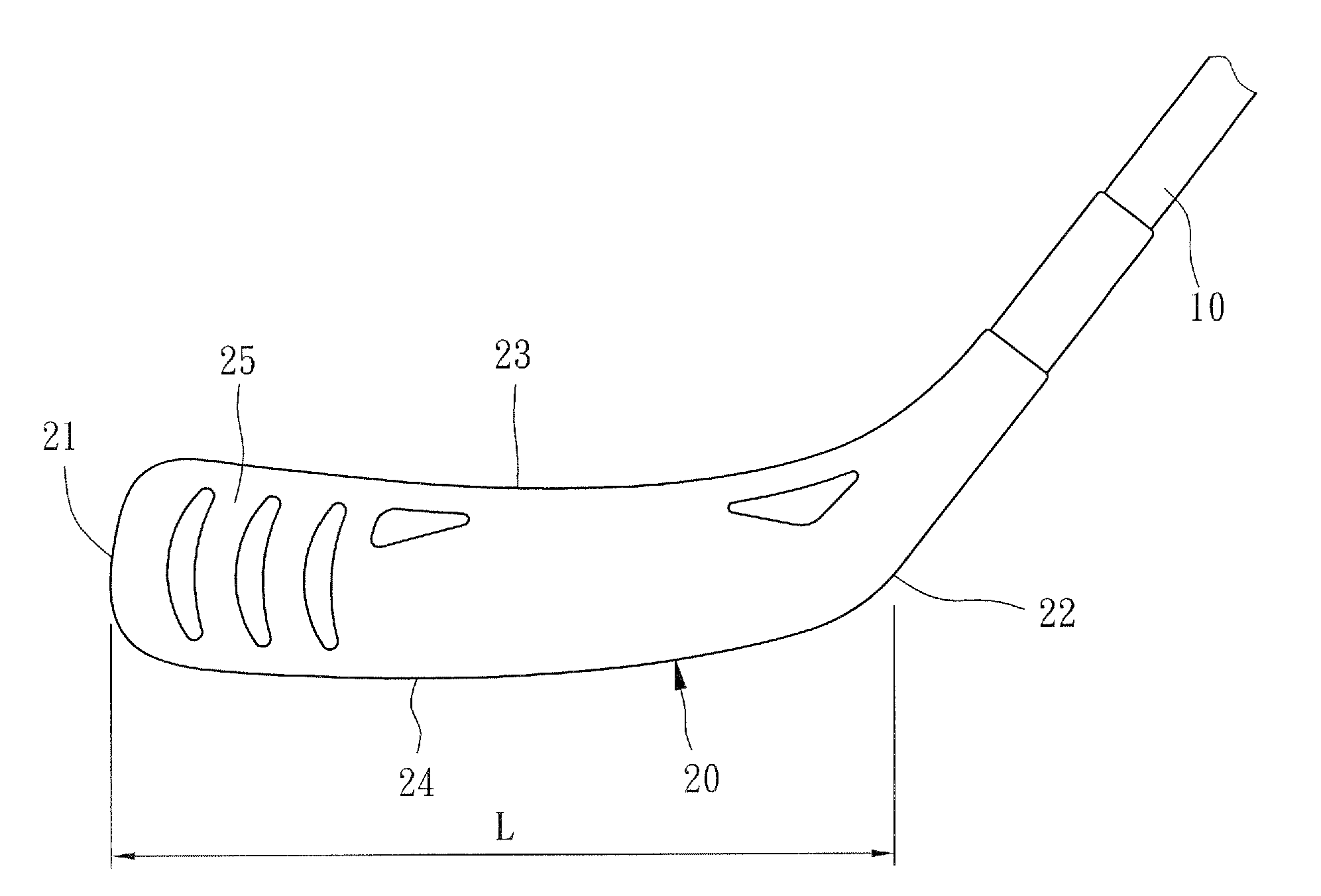
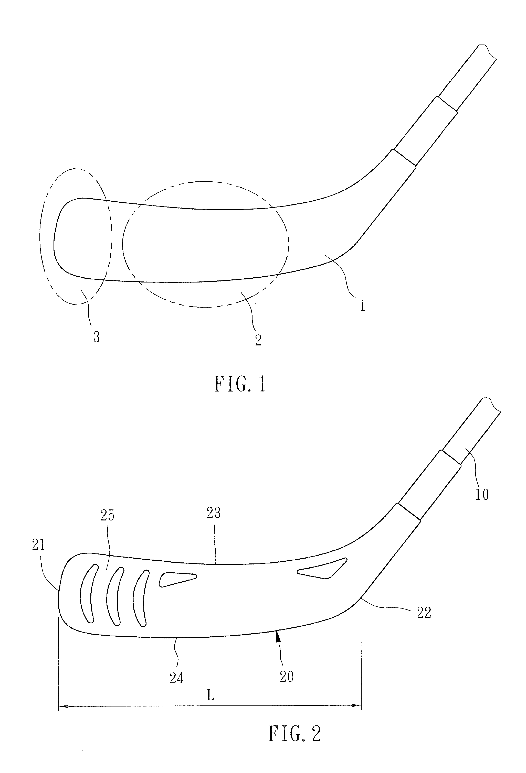
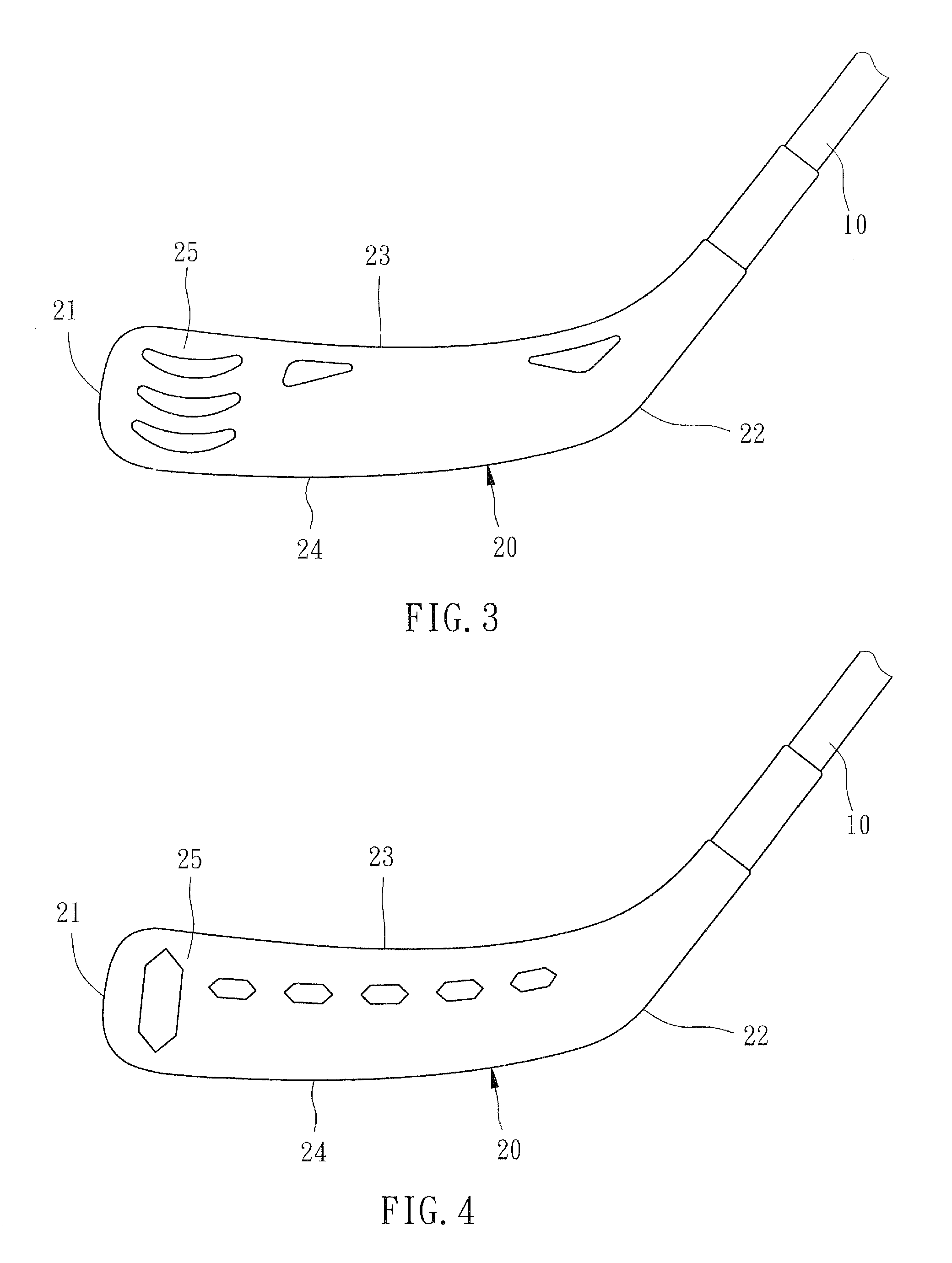
[0011]As shown in FIG. 2, a hockey stick of the first preferred embodiment of the present invention includes a shaft 10, and a blade 20. The blade 20 includes a toe end 21, a heel end 22, a top edge 23 and a bottom edge 24. A transverse length of the blade 20 is defined as L. The blade 20 has an opening portion 25 within a region between the toe end 21 and ⅓ L from the toe end 21. In the present embodiment, the opening portion 25 includes a plurality of parallel vertical openings to increase a flexibility of the region of the blade 20 adjacent to the toe end 21.

[0012]The advantages of hockey stick the present invention with the opening portion 25 include:

[0013]1. The region with the opening portion 25 is more flexible than a center region of the blade that the player can pick and pitch the puck faster and precisely.

[0014]2. The opening portion 25 may reduce the weight of the blade 20 about 15% to 20% (Typically, the blade is about 80 g to 100 g, and the opening portion 25 may reduce...


PUM


Abstract

A hockey stick includes a shaft and a blade. The blade has a toe end, a heel end, a top edge and a bottom edge. The blade has an opening portion within a region between the toe portion and 1 / 3 of a length between the toe portion and the heel portion of the blade from the toe portion.

Description

BACKGROUND OF THE INVENTION[0001]1. Field of the Invention[0002]The present invention relates generally to an ice hockey stuff, and more particularly to a hockey stick.[0003]2. Description of the Related Art[0004]FIG. 1 shows a conventional ice hockey stick, which has a blade 1. The hockey players usually swing the hockey stick to drive the puck by various skills, such as hit, pick, and pitch. With the different skills, the hockey players have to hit the puck by different portions of the blade. Basically, hit needs more power, so that players have to hit the puck by a main portion 2 at a center of the blade 1. The main portion 2 should be the strongest area of the blade 1. Pick and pitch need flexibility and speed rather than power, so that player has to hit the puck by a front portion 3 adjacent to a toe end of the blade 1. The front portion 3 should be soft and more flexible. However, the conventional hockey sticks have the entire blade with the same property so that the blade can...

Claims


Application Information

Patent Timeline
IPC IPC(8): A63B59/14
CPCA63B49/06A63B59/14A63B59/0088A63B2102/24A63B59/70A63B60/52A63B60/50A63B60/00
Inventor SHIU, HSIU CHENG
Owner SHIU HSIU CHENG
Learn More