

Connector Connecting a Windscreen-Wiper Blade to a Drive Arm
- Summary
- Abstract
- Description
- Claims
- Application Information
AI Technical Summary
Benefits of technology
Problems solved by technology
Method used
Image

Examples
first embodiment
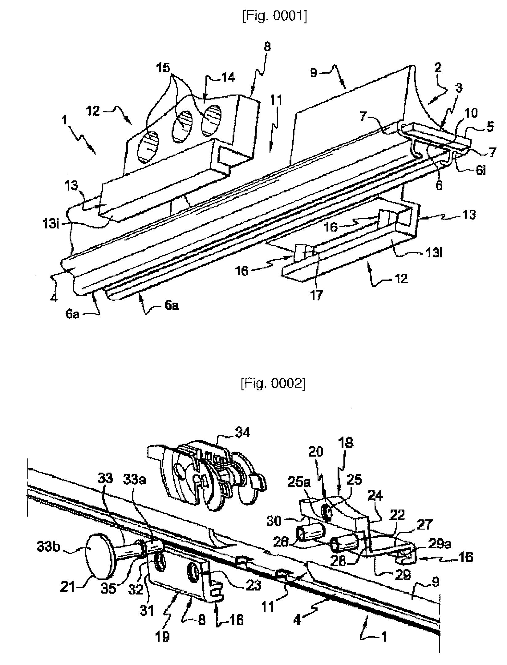
[0087]FIG. 2 shows a perspective view before assembly of a connector according to the invention prior to assembly on the windscreen-wiper blade 1.
[0088]The connector 8, providing the connection between a windscreen-wiper blade 1 and a drive arm (not shown but of a known type), consists of a pair of flanges (18, 19) capable of cooperating with one another and of being solidly attached on the windscreen-wiper blade 1.
[0089]The pair of flanges (18, 19) advantageously consists of a primary flange or axis-supporting flange, hereinafter denoted 18, and a secondary flange 19.
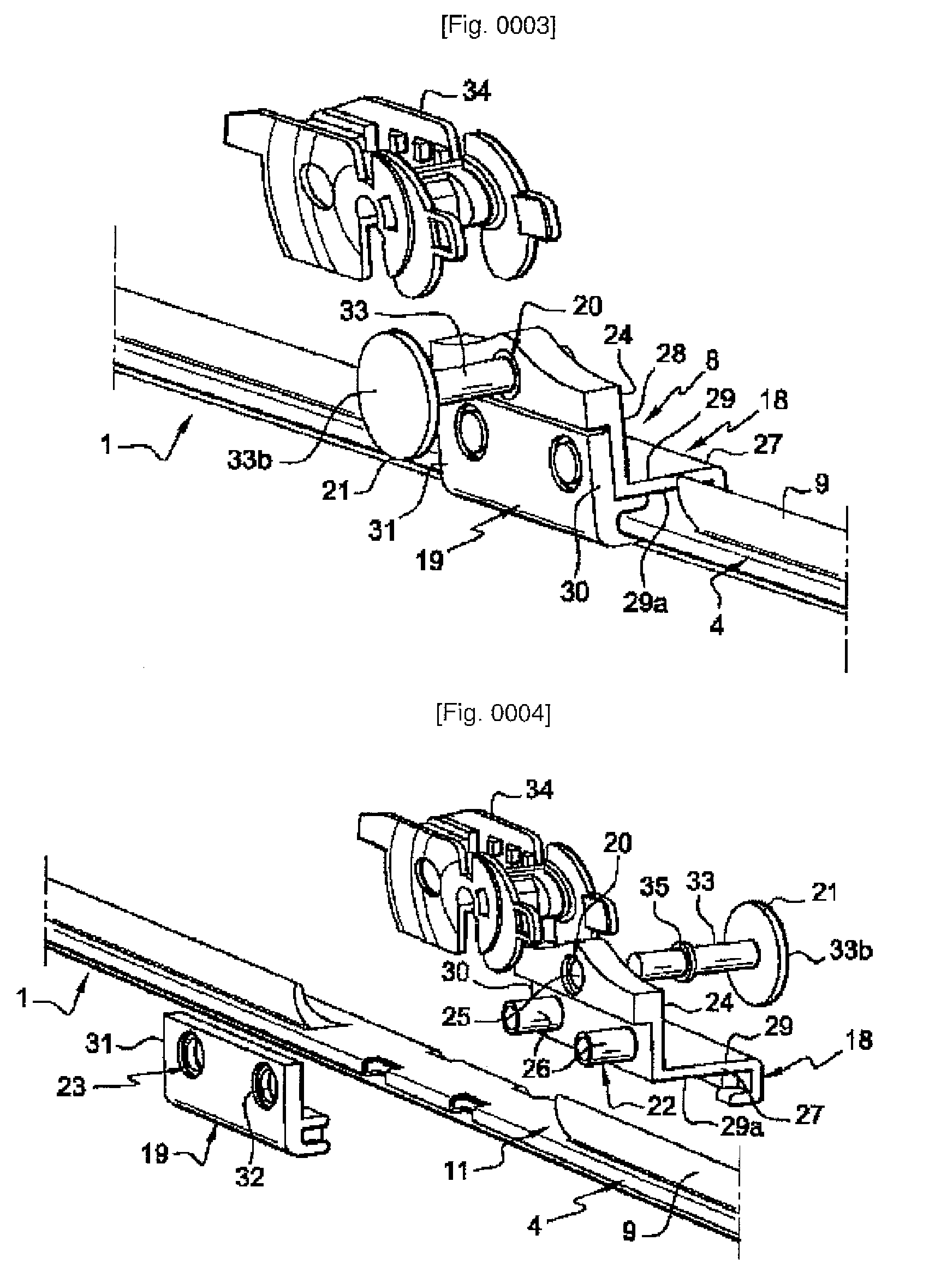
[0090]The primary flange 18 has means for fixing 20 an axis of rotation 21 as well as means for solid attachment 22 with attachment means 23 having a matching shape on the secondary flange 19.
[0091]The primary flange 18 has a general L shape and consists of:[0092]a top collar 24 having fixing means 20 for an axis of rotation 21 in the form of an orifice 25 as well as attachment means 22 in the form of a pair of lugs 26...
third embodiment
[0144]FIG. 11 is a perspective view of a connector according to the invention for a side-lock link.
[0145]More precisely, the connector according to this embodiment consists of two identical flanges 49 each having locking means 16 with lugs 17 surrounded by lateral tabs 36 such as previously described.
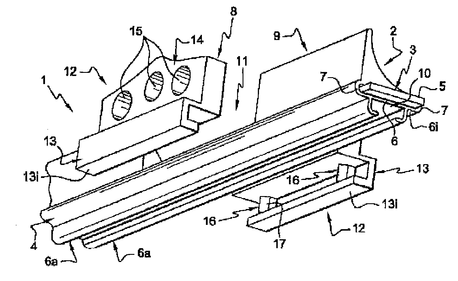
[0146]Each flange 49 consists of a top collar 14 in the form of a flank and a bottom collar 13 including said locking means 16.
[0147]The top collar 14 of the flange 49 has attachment meant 15 capable of cooperating with the attachment means 15 of the other flange 49 when they are fixed on the central body 4 of the windscreen-wiper blade 1.
[0148]More precisely, each top collar 14 has one orifice 50 and one lug 51, the orifice of the top collar 14 of a flange 49 being capable of being inserted in a lug 51 of another flange 49 when assembling and fixing the two flanges 49 on a windscreen-wiper blade 1 in order to form the connector according to the invention.
[0149]Also provided in each fla...
fourth embodiment
[0152]FIG. 12 is a perspective view during assembly of a connector according to the invention for a side-lock link.
[0153]According to this alternative embodiment, unlike in the third embodiment of the invention previously described in FIG. 11, the insertable end 33a of the cylindrical element 33 forming the axis of rotation 21 is only capable of being inserted in an orifice 52 of a flange 49 by crimping means of a known type.
PUM
 Abstract
Description
Claims
Application Information