Disc brake device

a disc brake and disc technology, applied in the direction of noise/vibration control, slack adjusters, braking elements, etc., can solve the problems that the disc brake apparatus described in patent document 1 and the disc brake apparatus described in patent document 2 cannot be expected to securely restrain clunking sounds from occurring, so as to achieve the effect of convenient us

Inactive Publication Date: 2009-01-08
TOYOTA JIDOSHA KK
View PDF8 Cites 12 Cited by
  • Summary
  • Abstract
  • Description
  • Claims
  • Application Information

AI Technical Summary

Benefits of technology

[0020]In the disc brake apparatus in accordance with the present invention, the switching holding means holds the disc brake apparatus in the first contact state where the first torque transmission part of the brake pad abuts against the first torque receiving part of the torque member along with an operation for normal braking of the disc rotor (forward braking of the vehicle), and switches the disc brake apparatus to and holds the second contact state where the second torque transmission part of the brake pad abuts against the second torque receiving part of the torque member along with an operation for reverse braking of the disc rotor (back braking of the vehicle), whereby clunking sounds can securely be suppressed not only at the time of normal braking of the disc rotor (forward braking of the vehicle) but also at the time of reverse braking of the disc rotor (back braking of the vehicle).
[0021]Here, the disk brake apparatus of the present invention in which the switching holding means is constructed such as to switch the disc brake apparatus to and hold the first or second contact state by a magnetic force makes it unnecessary to change forms of brake pads and pad retainers, and thus can easily be employed in conventional disc brake apparatus. Since it does not depend on elastic forces which may vary over years, the first or second contact state can be held by a stable holding force over a long period of time.

Problems solved by technology

Meanwhile, the disc brake apparatus described in Patent Document 1 cannot be expected to securely restrain clunking sounds from occurring at the time of back braking of the vehicle, since it only has a structure in which the second torque transmission part of the brake pad to become the turning-out side of the disc rotor at the time of back braking of the vehicle is simply elastically received by the second spring action part of the second pad retainer.
Similarly, the disc brake apparatus described in Patent Document 2 cannot be expected to securely restrain clunking sounds from occurring at the time of back braking of the vehicle, since it only has a structure in which the second torque transmission part of the brake pad to become the turning-out side of the disc rotor at the time of back braking of the vehicle is simply received by the spring force of the second anti-clunk part of the pad shim.

Method used


Image

  • Disc brake device
  • Disc brake device
  • Disc brake device

Examples


first embodiment

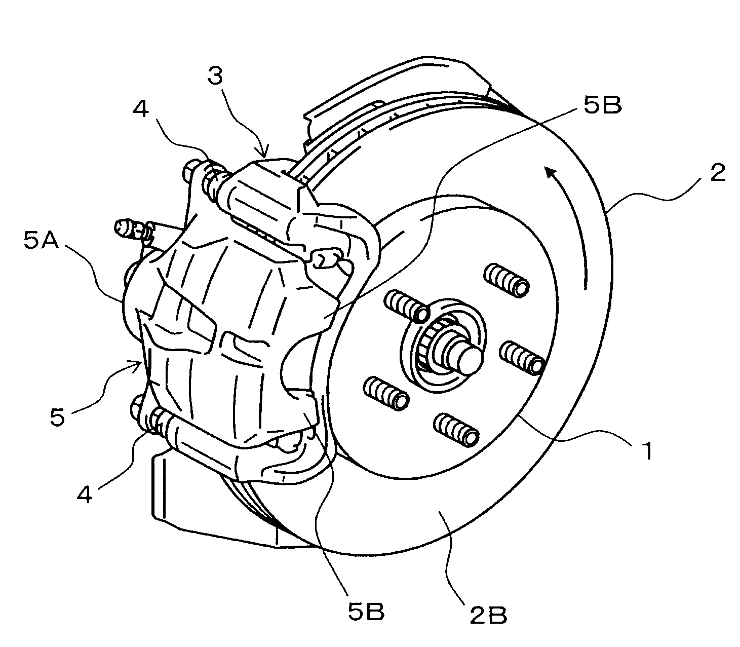
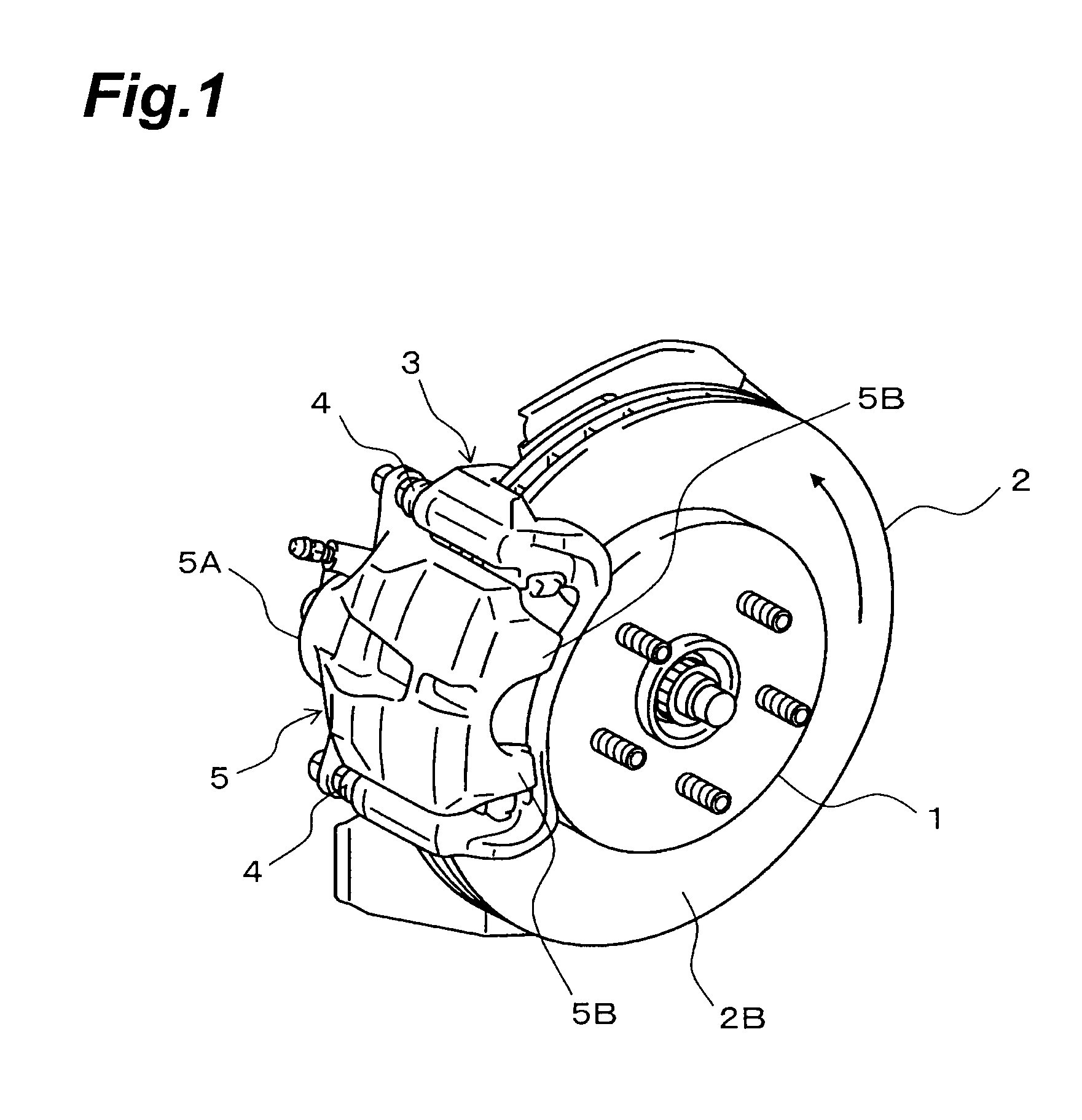
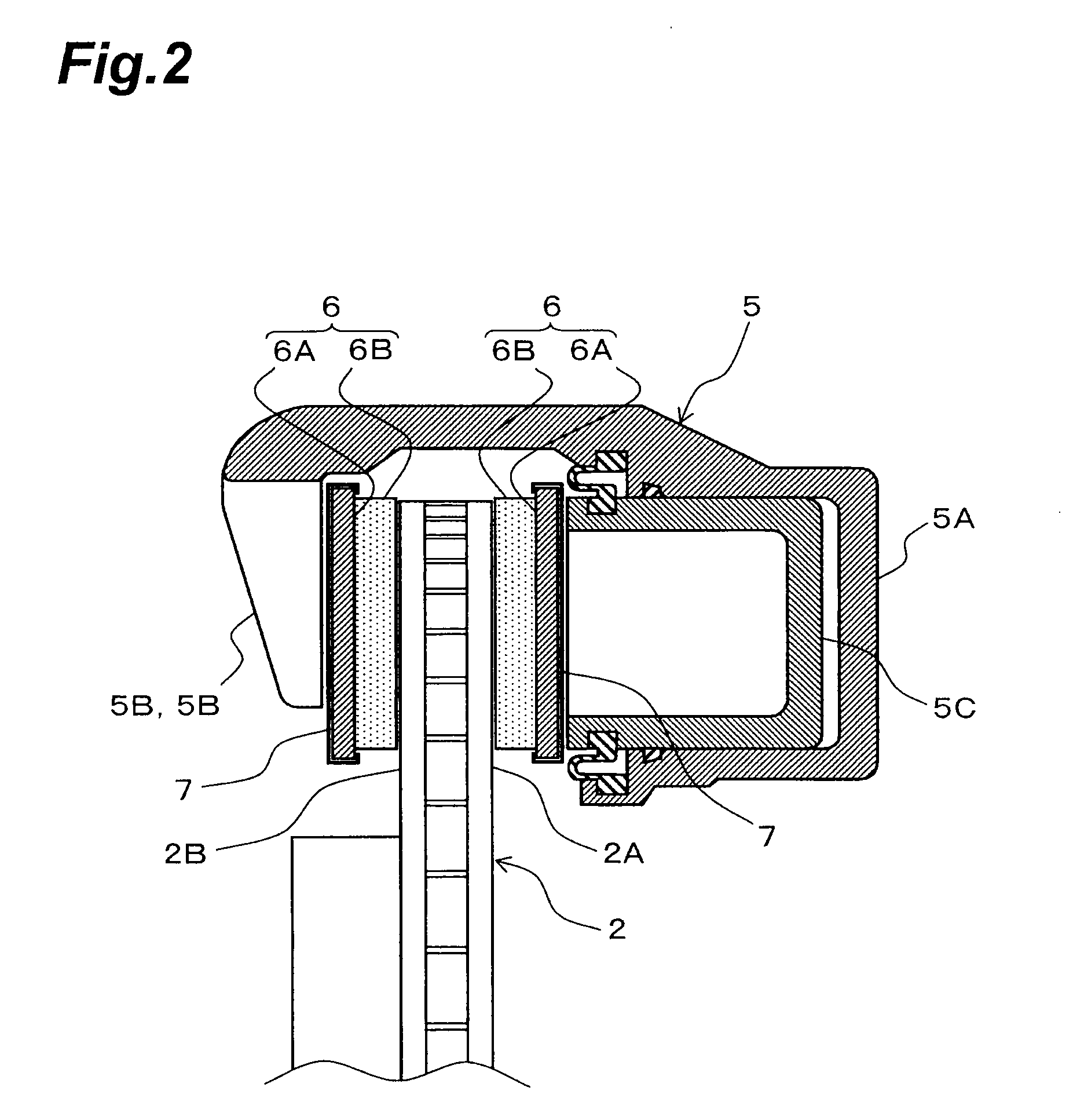
[0045]In the following, embodiments of the disc brake apparatus in accordance with the present invention will be explained with reference to the drawings. Among the drawings for reference, FIG. 1 is a perspective view showing the exterior of the disc brake apparatus in accordance with the present invention, FIG. 2 is a partial sectional view schematically showing a cross-sectional structure of a caliper in the disc brake apparatus shown in FIG. 1, and FIG. 3 is a side view schematically showing the disc brake apparatus shown in FIG. 1.

[0046]The disc brake apparatus in accordance with the first embodiment, which is constructed for a vehicle, comprises a disc rotor 2 which is secured to a hub 1 of an axle so as to rotate integrally therewith, a torque member 3 which is supported by a suspension part or the like (not depicted) of a vehicle body and arranged such as to stride over an outer peripheral part of the disc rotor 2, and a floating caliper 5 which is attached to the torque memb...

second embodiment

[0067]The switching holding means of the disc brake apparatus in accordance with the second embodiment is constructed as shown in FIG. 9, for example. Namely, in the second torque transmission part 6D of the backing metal 6A of the brake pad 6, a pair of first engaging recesses 6G, 6G and a pair of second engaging recesses 6H, 6H are formed adjacent to each other on both surfaces facing the inner and outer sides of the disc rotor 2 in the radial direction. Correspondingly, the second pad retainer 9 attached to the second torque receiving part 3D of the torque member 3 is integrally formed with a pair of spring pieces 9B, 9B.

[0068]The pair of first engaging recesses 6G, 6G and the pair of second engaging recesses 6H, 6H are formed like V-grooves, while the pair of spring pieces 9B, 9B have leading end parts bent such as to be selectively engageable with the first engaging recesses 6G, 6G or second engaging recesses 6H, 6H. Namely, when the brake pad 6 shifts toward the first torque r...

third embodiment

[0076]The switching holding means of the disc brake apparatus in accordance with the third embodiment is constructed as shown in FIG. 12, for example. Namely, a pair of first permanent magnets 11, 11 for attracting the first torque transmission part 6C of the backing metal 6A of the brake pad 6 are buried in the first torque receiving part 3C of the torque member 3, while a pair of second permanent magnets 12, 12 for attracting the second torque transmission part 6D of the backing metal 6A of the brake pad 6 are buried in the second torque receiving part 3D of the torque member 3.

[0077]The pair of first permanent magnets 11, 11 are arranged separately from each other in the radial direction of the disc rotor 2 such as to attract the first torque transmission part 6C of the backing metal 6A evenly. Similarly, the pair of second permanent magnets 12, 12 are arranged separately from each other in the radial direction of the disc rotor 2 such as to attract the second torque transmission...


PUM


Abstract

A disc brake apparatus which can securely suppress clunking sounds not only at the time of forward braking of a vehicle but also at the time of back braking of the vehicle is provided. When a backing metal 6A of a brake pad 6 shifts toward a first torque receiving part 3C of a torque member 3 along with an operation for forward braking of the vehicle, a leading end part of a spring piece 9A engages one slope of an engaging projection 6E, so as to elastically press the backing metal 6A toward the first torque receiving part 3C, whereby the disc brake apparatus is held in a first contact state. When the backing metal 6A shifts toward a second torque receiving part 3D of the torque member 3 along with an operation for back braking of the vehicle, the leading end part of the spring piece 9A engages the other slope of the engaging projection 6E, so as to elastically press the backing metal 6A toward the second torque receiving part 3D, whereby the disc brake apparatus is held in a second contact state. As a result, the clunking sounds are suppressed not only at the time of forward braking of a vehicle but also at the time of back braking of the vehicle.

Description

TECHNICAL FIELD[0001]The present invention relates to a disc brake apparatus which is mounted as a braking apparatus to a vehicle, for example.BACKGROUND ART[0002]Disc brake apparatus have conventionally been known in general, in which rotor surfaces on both sides of a disc rotor are held by a pair of brake pads, while the rotary torque received by the brake pads from the rotor surfaces of the disc rotor is caught by a torque member (mounting), so as to obtain a braking force.[0003]In such a disc brake apparatus, the brake pads typically have a structure in which a backing metal is joined to a pad member coming into frictional contact with the rotor surface of the disc rotor, while the backing metal has a first torque transmission part set at an end part to become the turning-out side during normal rotations (the turning-in side during reverse rotations) of the disc rotor and a second torque transmission part set at an end part to become the turning-out side during reverse rotations...

Claims


Application Information

Patent Timeline
Patent Type & Authority Applications(United States)
IPC IPC(8): F16D55/00
CPCF16D65/0006F16D65/0972F16D65/095F16D65/092
Inventor SEKIYA, YOSHIHIDEISONO, HIROSHIYAMAGUCHI, YOSHIYUKI
Owner TOYOTA JIDOSHA KK
Why Eureka
Try Eureka