Endoscope system

a technology of endoscope and endoscope, which is applied in the field of endoscope systems, can solve the problems of increasing the temperature of the surroundings, requiring a large power consumption, and generating uneven colors, so as to improve the convenience of handling the endoscope system, and reduce the overall size of the endoscope system

Inactive Publication Date: 2006-10-19
FUJIFILM HLDG CORP +2
View PDF10 Cites 67 Cited by
  • Summary
  • Abstract
  • Description
  • Claims
  • Application Information

AI Technical Summary

Benefits of technology

[0015] Since, in the endoscope system having an insertion portion and a control portion connected to a base end portion of the insertion portion, the endoscope system of this invention is characterized by having an illumination means comprising a light guide having a front end which is positioned near the front end of the insertion portion and a rear end which is positioned rearward of the base end of the insertion portion, phosphors disposed in the light guide toward the front end thereof and an illumination light source which is positioned toward the rear end of the light guide and emits stimulating light exciting the phosphors, it is not necessary to position the light source in the insertion portion and accordingly, the endoscope system of this invention can emit illumination light without unevenness in color without increasing the temperature in the insertion portion.
[0016] Even when an image pick-up element such as a CCD is employed, that dark noise and the like in the image pick-up element is increased due to increase in the temperature to deteriorate in the S / N of the obtained image can be avoided.
[0017] When the illumination light source is positioned in the control portion, it is not necessary to establish connection of the light guide with the illumination light source by complicatedly running cable, whereby the overall size of the endoscope system can be reduced and convenience to handle of the endoscope system can be improved.
[0018] When a semiconductor light emitting element is employed as the illumination light source, the overall size of the endoscope system can be reduced and the endoscope system can be produced at low cost. Further, since the semiconductor light emitting element is smaller in power consumption as compared with a halogen lamp or a xenon lamp, the overall size of the power source for the light source can also be reduced. Further, since the semiconductor emitting element is better in light collection as compared with the above mentioned lamps, reduction of the diameter of the light guide is facilitated. The semiconductor light emitting element is easy to position in the control portion of the endoscope system.
[0019] When a semiconductor laser is employed as the light source, the light coupling efficiency between the semiconductor laser and the light guide is increased since a laser beam is easy to converge on a fine point, and the number of the semiconductor light emitting element can be reduced or the power consumption can be reduced. Further, when the light coupling efficiency is high, the amount of light to be projected onto the site other than the light inlet end of the light guide or to be scatter at the junction becomes less and accordingly, it becomes possible to suppress heat generation near the junction. Further, a light guide comprising a single optical fiber can be easily employed and, at the same time, the single optical fiber can be reduced in its diameter.
[0020] When the stimulating light is not shorter than 350 nm and not longer than 500 nm in wavelength, fluorescence light in a visible region can be efficiently emitted from the phosphors.

Problems solved by technology

However, such an illumination means involves a problem that it is cumbersome and requires a large power consumption, e.g., hundreds of watts is required for the light source.
However, when the three color semiconductor light emitting elements are used in combination, there is a problem that unevenness in color is generated.
However, since being a heating body, the semiconductor light emitting element can increase the temperature of the surroundings when it is used long.
Especially, as the insertion portion of the endoscope has been reduced in its diameter, the heat capacity of the insertion portion tends to reduce, and when a semiconductor light emitting element is positioned in the insertion portion, there is a fear that the temperature of the surroundings of the semiconductor light emitting element is elevated to an undesirable temperature.

Method used


Image

  • Endoscope system
  • Endoscope system
  • Endoscope system

Examples


first embodiment

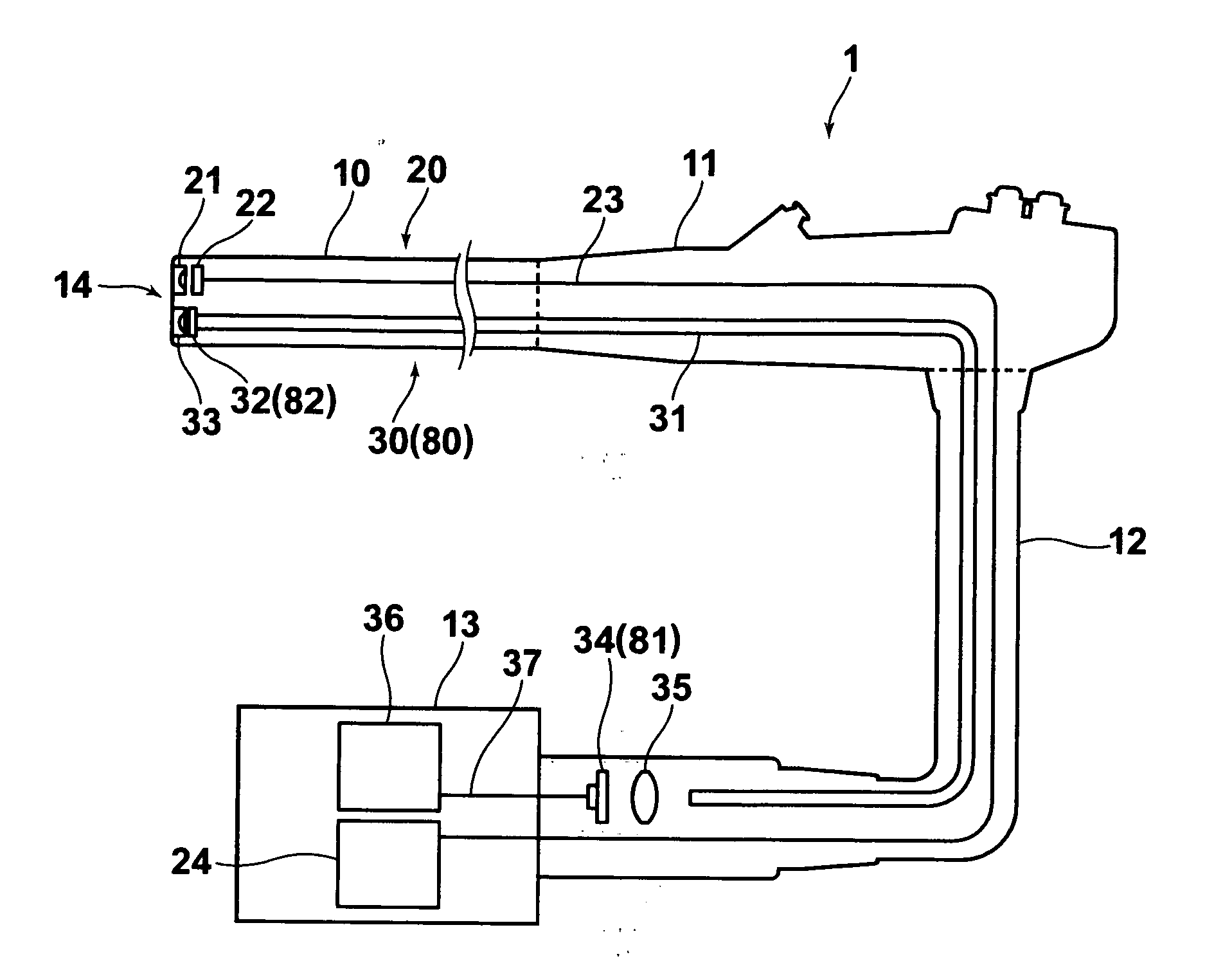
[0025] Fluorescence endoscope systems in accordance with embodiments of the present invention will be described with reference to the drawings, hereinbelow. In FIG. 1, a fluorescence system 1 in accordance with the present invention comprises an insertion portion 10 which is inserted into a body cavity or the like, a control portion 11 which is connected to a base end portion of the insertion portion 10 to control a bend or the like thereof, a universal cable 12 connected to the control portion 11 and a processor 13 removably connected to the universal cable 12. The processor 13 is connected to a monitor not shown. Further, the processor 13 effects a general control of the endoscope system including drive of a CCD 22 and a semiconductor laser 34 to be described later.

[0026] The insertion portion 10 comprises a soft portion and an angle portion which is connected to the soft portion and directs a front end portion 14 of the insertion portion 10 in a desired direction.

[0027] The endo...

second embodiment

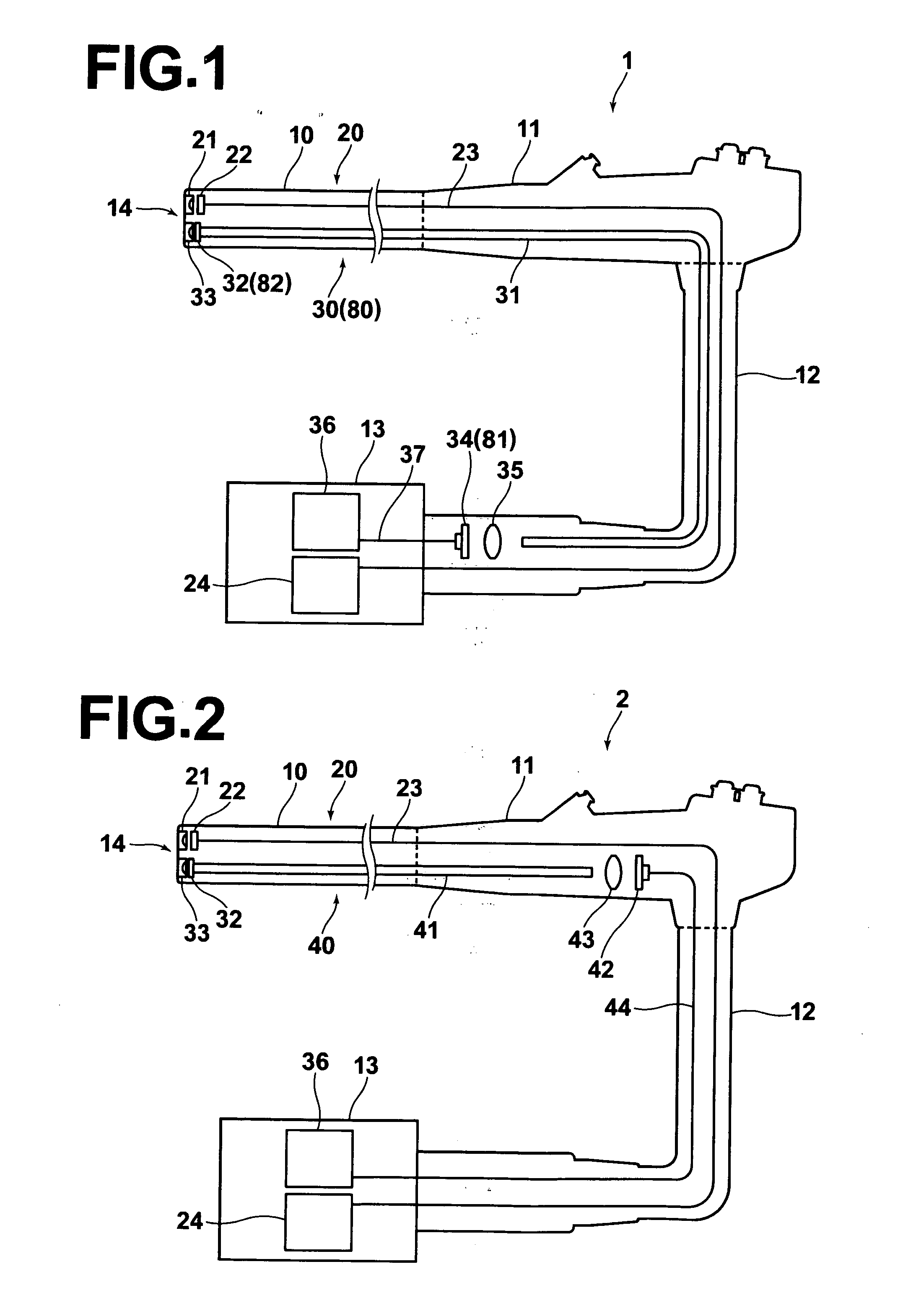
[0039] An endoscope system in accordance with the present invention will be described with reference to FIG. 2, hereinbelow. In the endoscope system 2 of this embodiment, the light source of the illumination means is disposed in the control portion. The elements analogous to those shown in FIG. 1 are given the same reference numerals and will not be described unless necessary.

[0040] The illumination means 40 comprises a light guide 41 which is positioned in the front end portion 14 of the insertion portion 10 at its front end and in the control portion 11 at its rear end, phosphors 32 positioned on the side of the light guide 31 near the front end thereof or in the front end portion 14 of the insertion portion 10, an illumination lens 33 provided in front of the phosphors 32, a semiconductor laser 42 which is positioned in the control portion 11 near the rear end of the light guide 31 and emits a laser beam which excites the phosphors 32, a collective lens 43 which collects the lase...

third embodiment

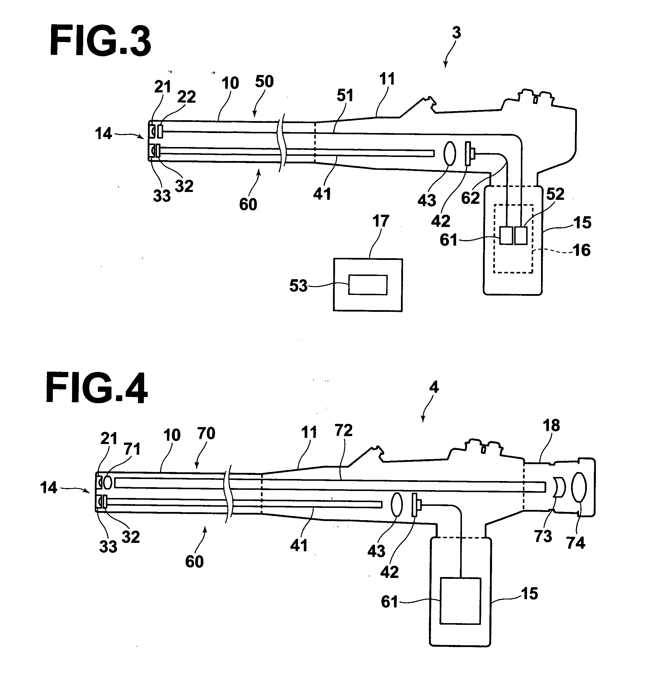
[0044] An endoscope system in accordance with the present invention will be described with reference to FIG. 3, hereinbelow. The endoscope system 3 of this embodiment is in the form of a portable endoscope where no universal cable is necessary. The elements analogous to those shown in FIG. 1 are given the same reference numerals and will not be described unless necessary.

[0045] As shown in FIG. 3, the endoscope system 3 comprises an insertion portion 10 which is inserted into a body cavity or the like, a control portion 11 which is connected to a base end portion of the insertion portion 10, an extension 15 connected to the control portion 11 and a processor 17 remote from the endoscope body. A simplified processor 16 is provided in the extension 15.

[0046] The endoscope system 3 is further provided with an observing means 50 and an illumination means 60. The observing means 50 and the illumination means 60 are accommodated in the insertion portion 10, control portion 11 and the ext...


PUM


Abstract

An endoscope system has an insertion portion and a control portion connected to a base end portion of the insertion portion. An illumination system includes a light guide having a front end positioned near the front end of the insertion portion and a rear end positioned rearward of the base end of the insertion portion, phosphors disposed in the light guide toward the front end thereof and an illumination light source which is positioned toward the rear end of the light guide and emits stimulating light exciting the phosphors.

Description

BACKGROUND OF THE INVENTION [0001] 1. Field of the Invention [0002] This invention relates to an endoscope system having an insertion portion and a control portion connected to a base end portion of the insertion portion, and more particularly to an endoscope system provided with an illumination means for radiating illumination light from the front end of the insertion portion. [0003] 2. Description of the Related Art [0004] There has been known, as an illumination means for an endoscope system for medical or industrial use, an illumination means comprising a light source such as a halogen lamp or a xenon lamp, and a light guide which comprises a fiber bundle and transfers illumination light to the front end of the insertion portion. However, such an illumination means involves a problem that it is cumbersome and requires a large power consumption, e.g., hundreds of watts is required for the light source. Accordingly, there has been developed an endoscope having an illumination mean...

Claims


Application Information

Patent Timeline
Patent Type & Authority Applications(United States)
IPC IPC(8): A61B1/06
CPCA61B1/0653A61B1/05A61B1/07
Inventor OHKUBO, KAZUNOBUHATORI, MASAMITAKEUCHI, SHINJIANDO, TADASHI
Owner FUJIFILM HLDG CORP
Why Eureka
Try Eureka