Liquid crystal display device and driving method for the same
Inactive Publication Date: 2005-12-15
SAMSUNG ELECTRONICS CO LTD
View PDF3 Cites 62 Cited by
Summary
Abstract
Description
Claims
Application Information
AI Technical Summary
This helps you quickly interpret patents by identifying the three key elements:
Problems solved by technology
Method used
Benefits of technology
Benefits of technology
[0012] The present invention provides a liquid crystal display (LCD) device, which can easily employ a rendering driving method of displaying high-resolution images. The present invention also provides an LCD device, which can perform a two-dot inversion with an excellent display characteristic and can perform a regular inversion driving of green, blue, and red pixels. Further, the present invention provides an LCD device with improved luminance.
[0013] The present invention also provides a driving method of an LCD device, which can minimize a driving constraint by inverting the polarity of a data voltage flowing through one data line by frame and can perform a two-dot inversion for an apparent pixel inversion. In addition, the present invention provides a driving method of an LCD device, which can minimize the driving constraint by inverting the polarity of the data voltage flowing through one data line and can prevent a vertical flicker phenomenon and vertical crosstalk.
Problems solved by technology
The PenTile Matrix pixel arrangement also increases the number of low-cost gate driving ICs, but decreases the number of high-cost data driving ICs.
However, the vertical inversion driving method causes a vertical flicker phenomenon and vertical crosstalk.
However, since the dot inversion driving method must invert the polarities of the data voltage for the predetermined column and row, the operation of applying the data voltage to data lines is complicated and results in a serious problem of signaldelay in the data lines.
Accordingly, the data lines are made of a low resistance material to reduce the signaldelay, increasing the complexity and cost of manufacturing.
Furthermore, in the case where the polarities of red pixels, green pixels, and blue pixels are irregular when performing the inversion on the LCD device having the PenTile Matrix pixel arrangement, the flicker phenomenon occurs and a luminance difference is generated between pixel columns, resulting in a deteriorated display quality of the LCD device.
Method used
Image
Click on the blue label to locate the original text in one second.
Reading with bidirectional positioning of images and text.
Examples
first embodiment
[0032] A liquid crystal display (LCD) device and a method of driving the same according to the present invention will now be described.
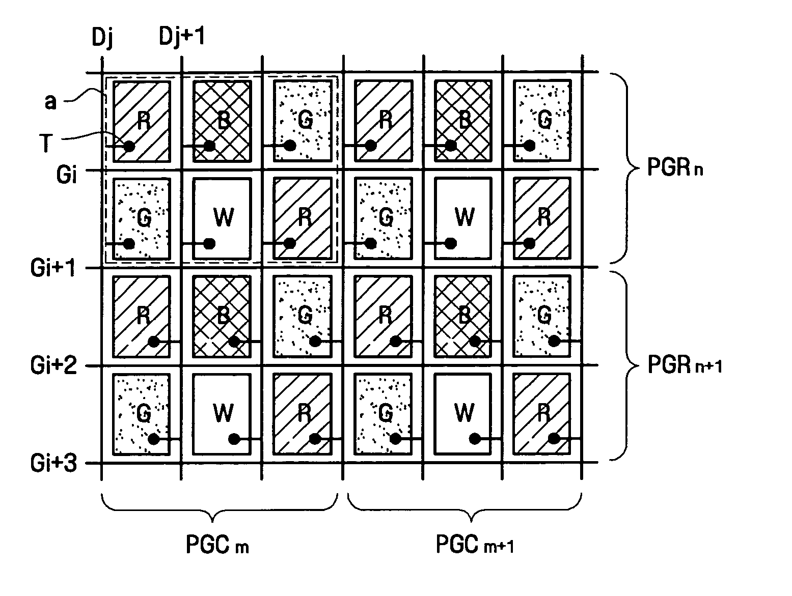
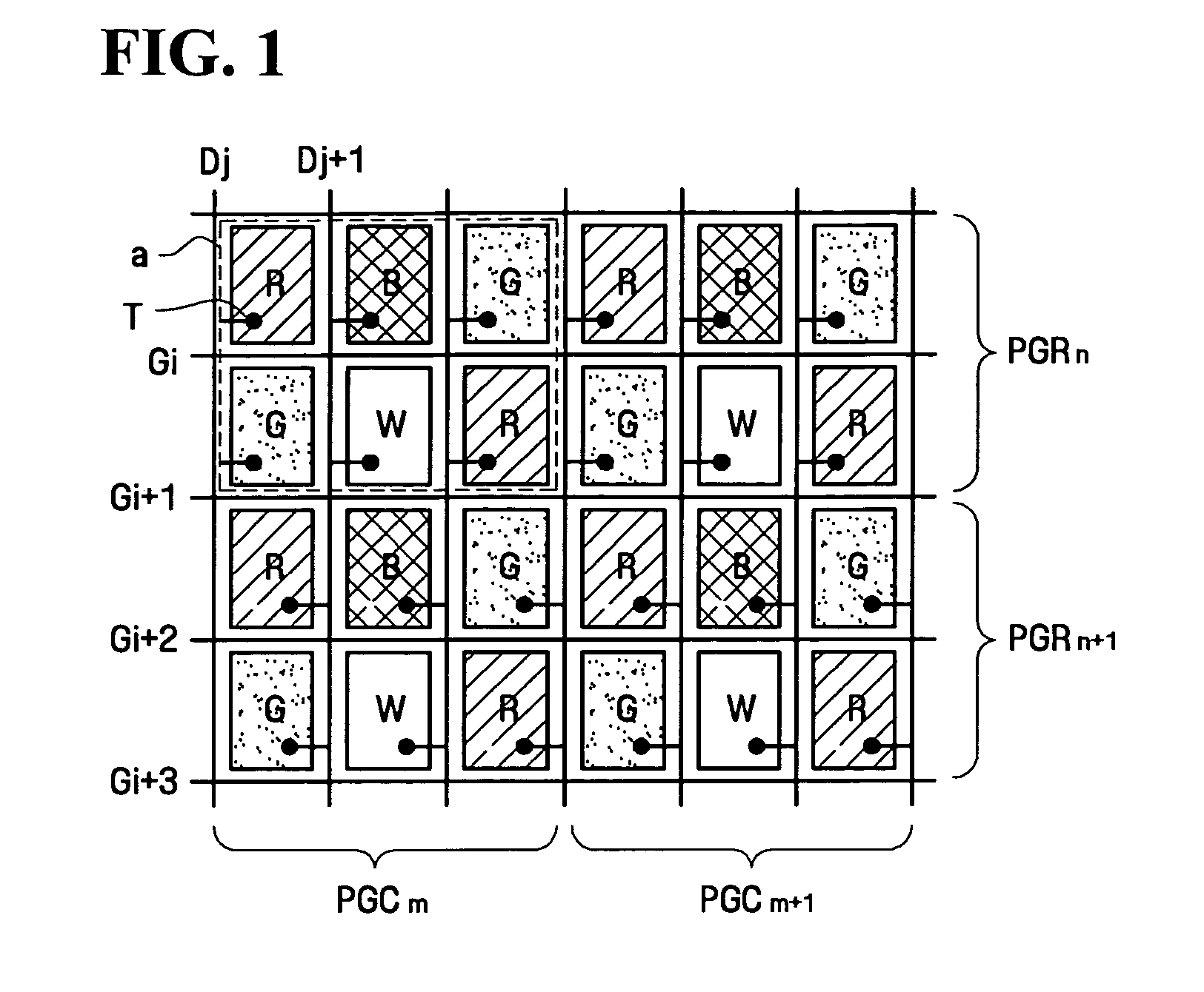
[0033]FIG. 1 is a schematic diagram illustrating an arrangement of pixels and switching devices in an LCD device according to the first embodiment of the present invention.
[0034] Referring to FIG. 1, the LCD according to the first embodiment of the present invention includes color filters of red pixels R, blue pixels B, green pixels G, and white pixels W, arranged in a matrix pattern. The red pixel R of the first row is arranged in the same column as the green pixel G of the second row, the blue pixel B of the first row is arranged in the same column as the white pixel W of the second row, and the green pixel G of the first row is arranged in the same column as the red pixel R of the second row. Thus, the red pixels R of the first and second rows face each other diagonally from opposite sides of the blue pixel B and the white pixel W. Similarly, the...
second embodiment
[0059] Next, an LCD and a driving method thereof according to the present invention will be described in greater detail.
[0060]FIG. 6 is a schematic diagram illustrating an arrangement of pixels and switching devices in the LCD device according to the second embodiment of the present invention, and FIG. 7 illustrates the arrangement of pixels and a TFT substrate of the LCD device according to the second embodiment of the present invention.
[0061] As shown in FIGS. 6 and 7, most structure of the LCD device according to the second embodiment of the present invention is the same as that of the LCD device according to the first embodiment of the present invention, except for the arrangement of the pixels and some portions of the structure.
[0062] In the LCD device according to the second embodiment of the present invention, red pixels R, blue pixels B, green pixels G, and white pixels W are arranged in a matrix pattern. The matrix pattern includes, a red pixel R, a blue pixel B, a green ...
third embodiment
[0068] An LCD device and a driving method thereof according to the present invention will now be described.
[0069]FIG. 8 is a schematic diagram illustrating an arrangement of pixels and switching devices in the LCD device according to the third embodiment of the present invention, and FIG. 9 illustrates the arrangement of pixels and a TFT substrate of the LCD device according to the third embodiment of the present invention.
[0070] As shown in FIGS. 8 and 9, the structure of the LCD device according to the third embodiment of the present invention is the same as that of the LCD device according to the first or second embodiment of the present invention, except for the arrangement of the pixels, and the LCD device according to the third embodiment of the present invention can be driven by the same driving method as the LCD device according to the first embodiment of the present invention.
[0071] In the LCD device according to the third embodiment of the present invention, red pixels R...
PUM
Abstract
Provided are a liquid crystal display (LCD) device and a driving method thereof for displaying high-resolution images. The LCD device comprises a plurality of pixel groups including a first pixel and a second pixel arranged in a same pixel column of two adjacent pixel rows. Each of the first and second pixels forms a dot in combination with an adjacent pixel disposed at each side of the first and second pixels in a corresponding pixel row. A plurality of gate lines arranged for each pixel row in a horizontal direction to transfer a gate voltage to the respective pixels. A plurality of data lines formed in a vertical direction while traversing the gate lines and arranged for each pixel column to transfer a data voltage to the respective pixels. A switching device is formed in each pixel which has a first side and a second side. The switching devices formed at pixels of a first pixel group row are connected to the data lines on the first side, and switching devices formed at pixels of a second pixel group row are connected to the data lines of the second side.
Description
BACKGROUND OF THE INVENTION [0001] 1. Field of the Invention [0002] The present invention relates to an image display device, and more particularly, to a liquid crystal display (LCD) device for displaying high-resolution images and a driving method for the same. [0003] 2. Description of the Related Art [0004] In general, an LCD device has a liquid crystal material injected into a space between a color filter substrate on which common electrodes and color filters are formed, and a thin-film transistor (TFT) substrate on which TFT and pixel electrodes are formed. In such an LCD device, images are represented by changing an arrangement of liquid crystal particles by applying different potentials to the pixel electrodes and the common electrodes, thereby controlling the light transmittance of the liquid crystal. Controlling the light transmittance of the liquid crystal allows a control of light passing through the LCD. [0005] There are several types of arrangement of the color filters. ...
Claims
Application Information
Patent Timeline
Application Date:The date an application was filed.
Publication Date:The date a patent or application was officially published.
First Publication Date:The earliest publication date of a patent with the same application number.
Issue Date:Publication date of the patent grant document.
PCT Entry Date:The Entry date of PCT National Phase.
Estimated Expiry Date:The statutory expiry date of a patent right according to the Patent Law, and it is the longest term of protection that the patent right can achieve without the termination of the patent right due to other reasons(Term extension factor has been taken into account ).
Invalid Date:Actual expiry date is based on effective date or publication date of legal transaction data of invalid patent.

