
Modular block system

Active Publication Date: 2006-06-08
VYKING WALL SYST LLC +1
View PDF14 Cites 24 Cited by
  • Summary
  • Abstract
  • Description
  • Claims
  • Application Information

AI Technical Summary

Benefits of technology

[0008] In light of the foregoing comments, it will be recognized that a principal object of the present invention is to provide a modular block system that is of simple construction and design and which can be easily employed with highly reliable results.
[0009] Another object of the present invention is to provide a modular block system that is easy to use to construct both residential and commercial landscaping projects or applications.
[0010] A further object of the present invention is to provide a modular block system that is capable of being manufactured using a mold with each mold being capable of producing two, four, or more modular blocks.
[0011] Another object of the present invention is to provide a modular block system that can be used to construct various landscaping structures such as retaining walls, fences, sitting walls, columns, and steps.
[0012] A still further object of the present invention is to provide a modular block system in which each of the blocks can be tumbled to present a natural or weathered appearance.
[0014] A still further object of the present invention is to provide a modular block system that has a designation on each of the modular blocks within the modular block system that can be used to easily construct various landscaping structures using installation instructions.

Problems solved by technology

Even though these blocks are relatively inexpensive, they typically require complex installations to construct various landscaping structures.
Further, due to the weight of the blocks, they are sometimes difficult to carry or handle when constructing a landscaping structure.
Frequent hand or finger injuries occur when handling these blocks.

Method used


Image

  • Modular block system
  • Modular block system
  • Modular block system

Examples


Embodiment Construction

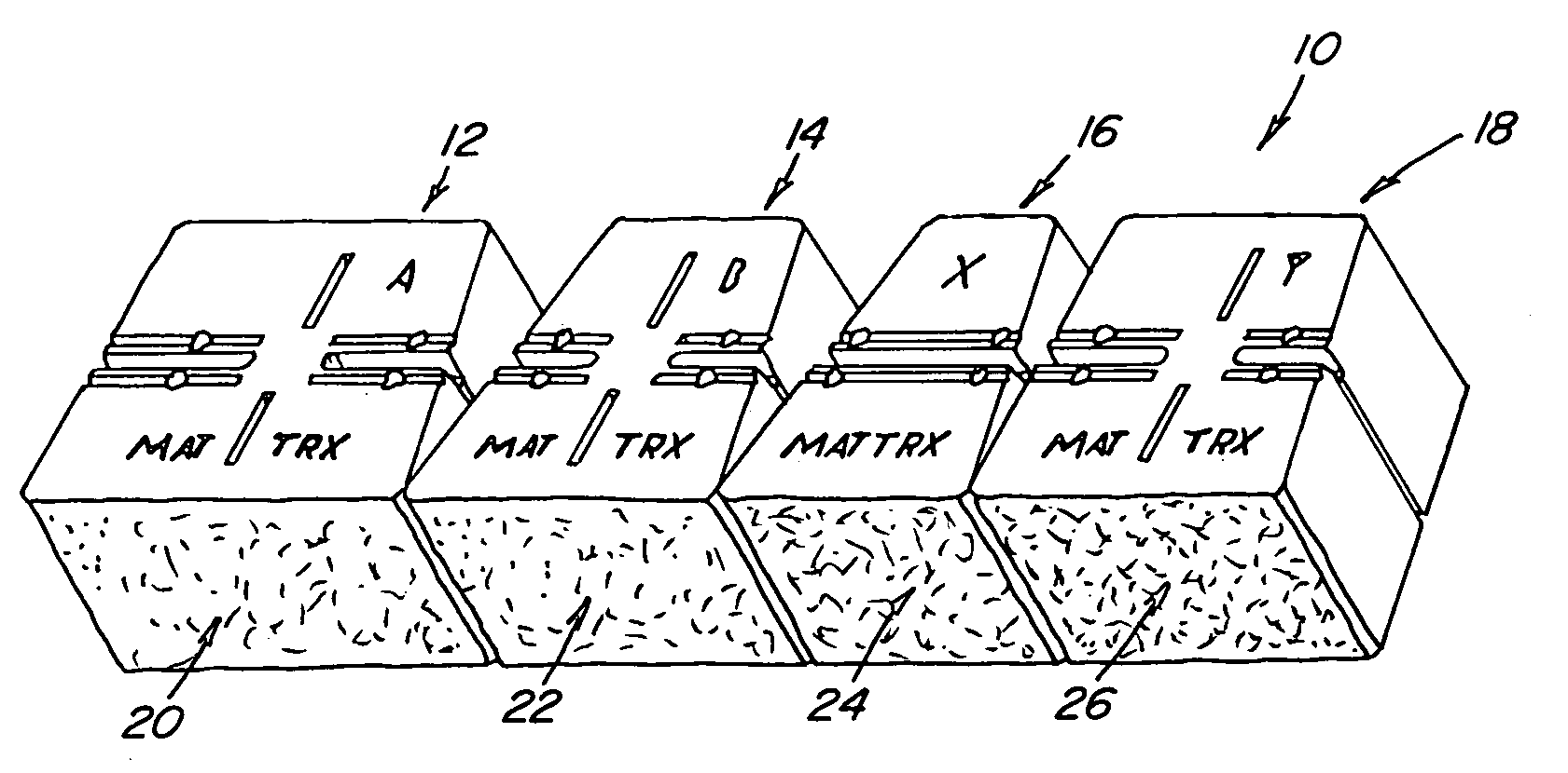
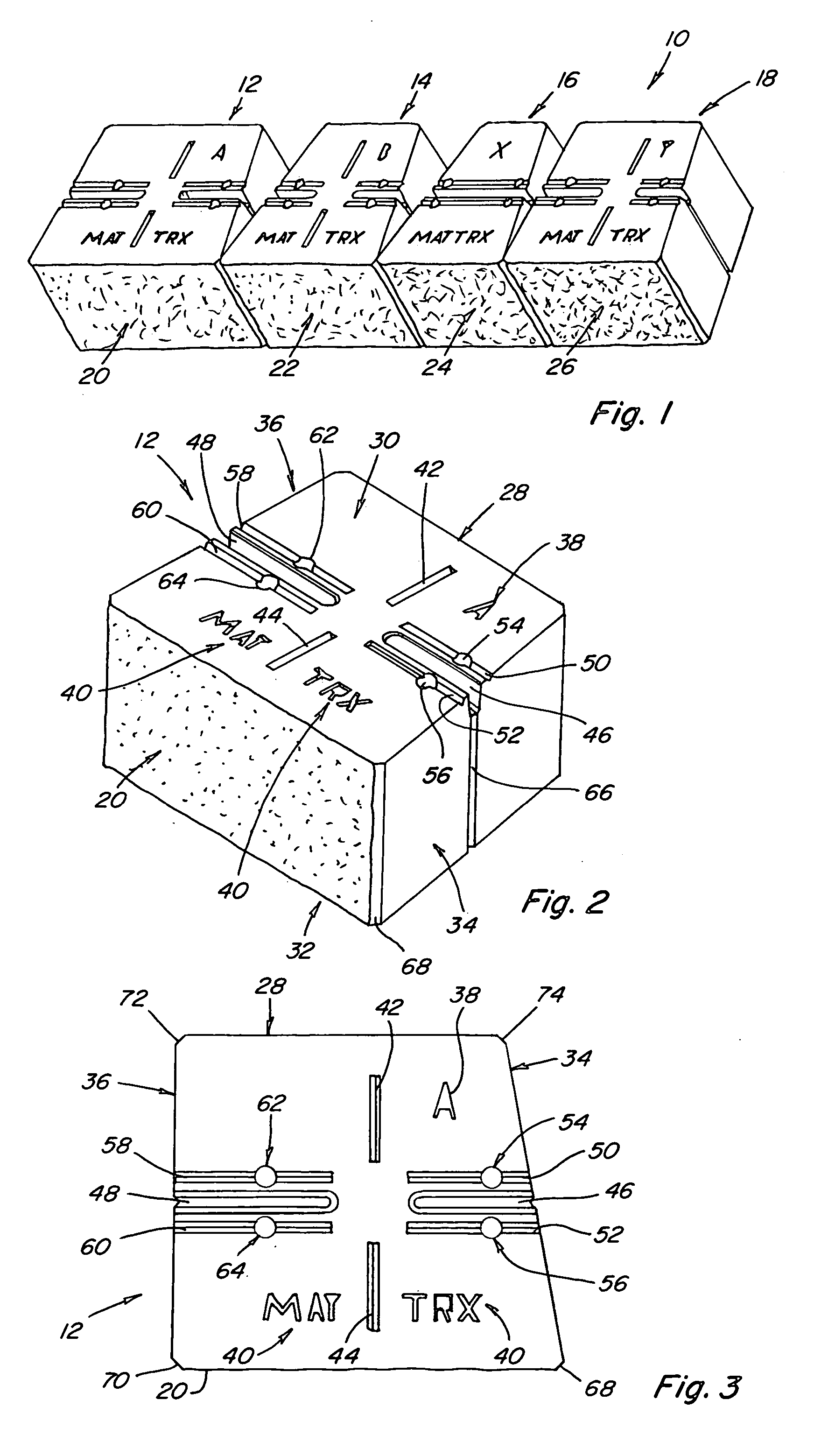
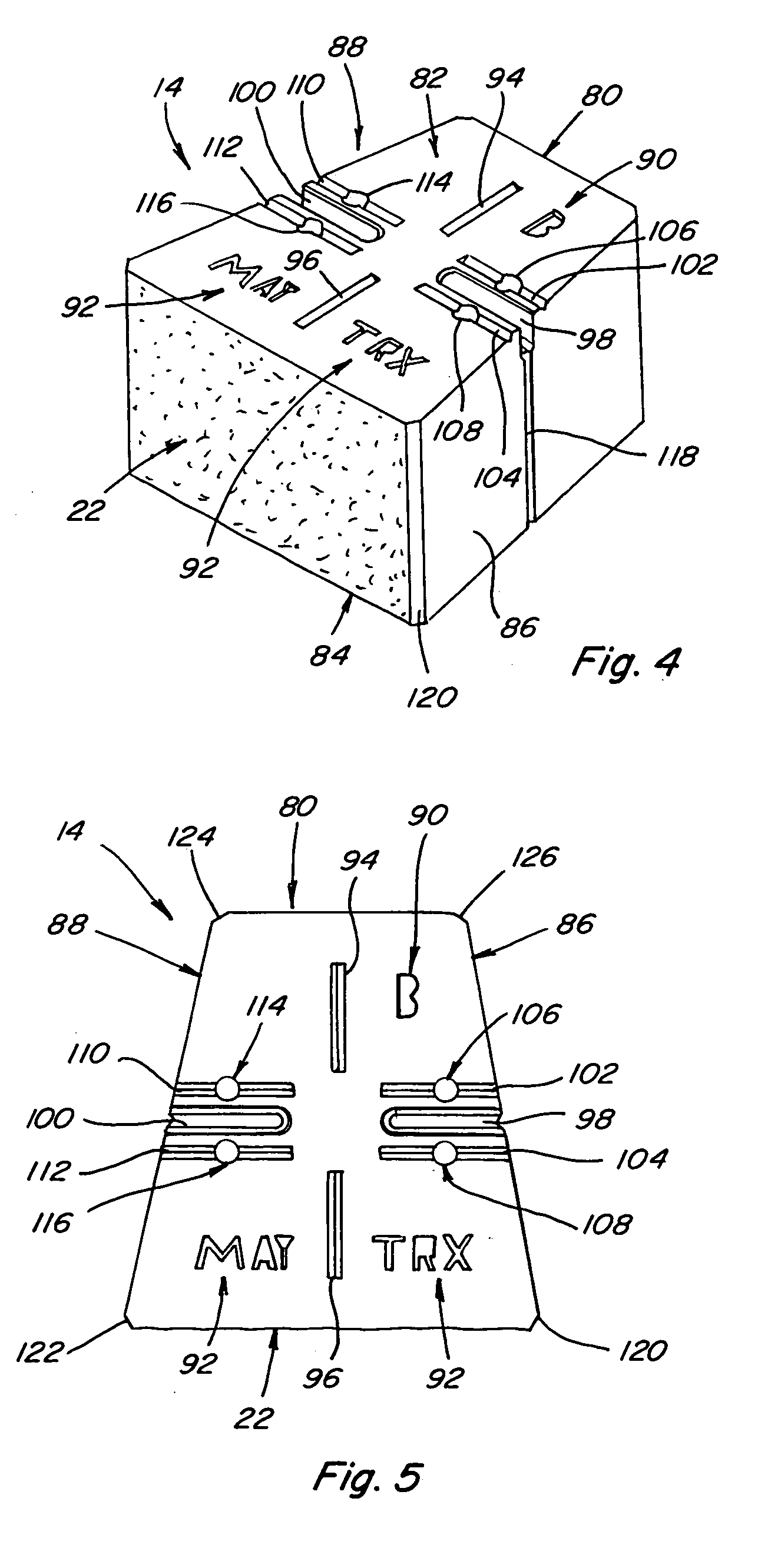
[0035] Referring now to the drawings, wherein like numbers refer to like items, number 10 identifies a preferred embodiment of a modular block system constructed according to the present invention. With reference now to FIG. 1, the modular block system 10 has a first block 12, a second block 14, a third block 16, and a fourth block 18. The modular block system 10 also has a cap stone block (not shown) that will be described in detail further herein. The first block 12 has a front face 20, the second block 14 has a front face 22, the third block 16 has a front face 24, and the fourth block 18 also has a front face 26. All of the front faces 20, 22, 24, and 26 have an irregular or textured surface that resembles a natural product such as rock or stone and is known as a split face. The manner in which the split face is formed will be described herein. The front faces 20, 22, 24, and 26 are used to form an irregular shaped course, wall, or pattern that resembles a structure formed of na...


PUM


Abstract

A modular block system comprises a first block, a second block, a third block, a fourth block, and a capstone, the first block having a front face, a back face, a first side, a second side, a top, and a bottom, with the front face being wider than the back face and the first side being slanted from the front face toward the back face, the second block having a front face, a back face, a first side, a second side, a top, and a bottom, with the front face being wider than the back face and the first and second sides being slanted from the front face toward the back face, the third block having a front face, a back face, a first side, a second side, a top, and a bottom, with the front face being wider than the back face and the first side being slanted from the front face toward the back face, and the fourth block having a front face, a back face, a first side, a second side, a top, and a bottom, with the front face being wider than the back face and the first side and the second side being from the front face toward the back face.

Description

BACKGROUND OF THE INVENTION [0001] This invention relates to a modular block system and more particularly to a modular block system for constructing a retaining wall or other similar landscaping structure. [0002] Retaining wall structures and similar landscaping structures have been constructed from various materials. Examples of such materials include railroad ties, steel rods or bars, poured concrete, rocks, stones, and preformed concrete blocks. In recent years the preformed concrete blocks have been popular because such blocks can be mass produced and are relatively inexpensive. Additionally, such blocks are as durable as concrete and have various finishes, textures, and colors. Even though these blocks are relatively inexpensive, they typically require complex installations to construct various landscaping structures. Further, due to the weight of the blocks, they are sometimes difficult to carry or handle when constructing a landscaping structure. Frequent hand or finger injur...

Claims


Application Information

Patent Timeline
IPC IPC(8): E04C2/04
CPCE04B2002/0245E04B2002/026E04B2002/0263E04C1/395
Inventor ADAM, PAUL
Owner VYKING WALL SYST LLC
Learn More