Facing multi-flange water-stop belt

A waterstop and veneer-type technology, which is applied in water conservancy projects, sea area projects, construction, etc., can solve the problems of weakening the strength of reinforced concrete structures, interfering with the design and construction of reinforced concrete structures, and achieves convenience in design and construction and guarantees strength Effect

Inactive Publication Date: 2015-09-09
YELLOW RIVER ENG CONSULTING
View PDF6 Cites 0 Cited by
  • Summary
  • Abstract
  • Description
  • Claims
  • Application Information

AI Technical Summary

Problems solved by technology

At present, the copper sheet waterstop and rubber waterstop used in water conservancy and hydropower projects have only one flange on each side. In order to achieve a certain water-stop effect, the width of the flange is generally greater than the thickness of the reinforced concrete protective layer. Therefore When arranging the steel bars of the concrete structure, in order to avoid the water stop, the steel bars of the concrete structure have to be bent inward, which weakens the strength of the reinforced concrete structure, and also causes great interference to the design and construction of the reinforced concrete structure

Method used


Image

  • Facing multi-flange water-stop belt
  • Facing multi-flange water-stop belt

Examples


Embodiment 1

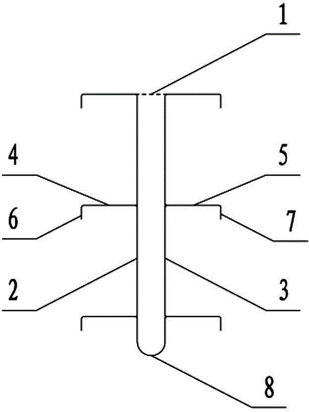
[0012] Such as figure 1 As shown, the veneer-type multi-flange waterstop of the present invention includes a waterstop body made of rubber material, the section shape of the waterstop body is a U-shaped structure, and the waterstop body is located The U-shaped opening of the body is provided with a rubber connecting diaphragm 1; the left veneer 2 and the right veneer 3 of the waterstop body are respectively provided with a left wing plate 4 and a right wing extending horizontally to both sides along the longitudinal direction of the waterstop body. Plate 5, the left and right wing plates 4, 5 are three layers arranged at intervals up and down respectively, and the outer edges of each layer of left and right wing plates 4, 5 are respectively downward vertically bent flanging structures 6, 7. The radius of the semicircular connecting section 8 at the lower end of the U-shaped waterstop body is adjusted according to the width of the concrete structure joint; the width of each lef...

Embodiment 2

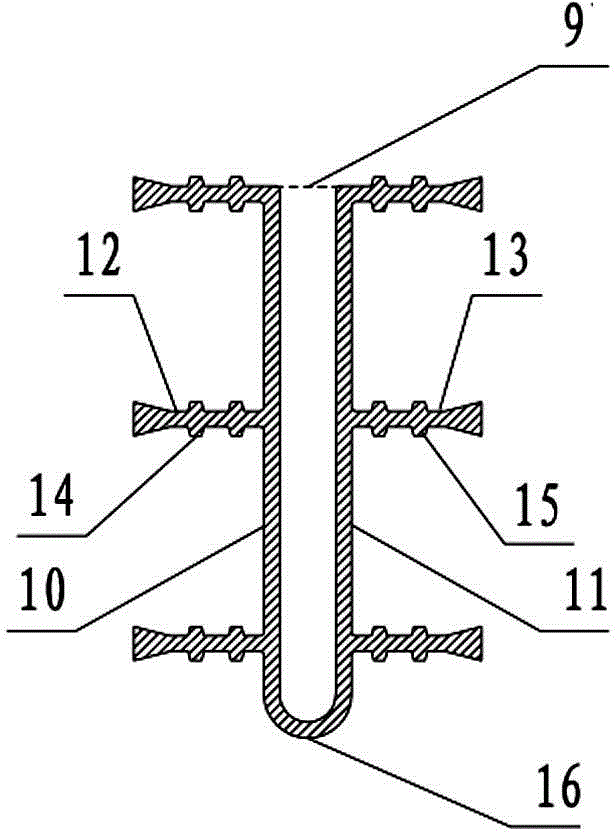
[0014] Such as figure 2 As shown, the veneer-type multi-flange waterstop of the present invention includes a waterstop body made of copper material, and the cross-sectional shape of the waterstop body is a U-shaped structure, located at The U-shaped opening of the waterstop body is provided with a copper connection diaphragm 9; the left veneer 10 and the right veneer 11 of the waterstop body are respectively provided with horizontally extending to both sides along the longitudinal direction of the waterstop body. Left wing plate 12 and right wing plate 13, said left and right wing plates 12, 13 are three layers arranged at intervals up and down respectively, and the upper and lower plates of each layer of left and right wing plates 12, 13 are spaced vertically along the waterstop body Ribs 14, 15 are provided. The radius of the semicircular connecting section 16 at the lower end of the U-shaped waterstop body is adjusted according to the width of the concrete structure joint...


PUM


Abstract

The invention discloses a facing multi-flange water-stop belt. The facing multi-flange water-stop belt comprises a water-stop belt body, wherein the shape of a section of the water-stop belt is of a U-shaped structure, and a connecting diaphragm is arranged at a U-shaped opening of the water-stop belt; the left face and right face of the water-stop belt body are respectively provided with left flange plates and right flange plates which extend horizontally to the two sides of the water-stop belt body along a longitudinal direction of the water-stop belt body, and the left and right flange plates are respectively arranged at intervals up and down. The facing multi-flange water-stop belt provided by the invention has the advantages of solving the problems that reinforcing steel bars are inwards bent to cause the weakening of the strength of a reinforced concrete structure by a primary water-stop belt during construction and the interference on the reinforced concrete structure and the construction can be caused by the water-stop belt, so that the strength of the reinforced concrete structure can be ensured, and the convenience can be provided to the design and construction of the reinforced concrete structure.

Description

technical field [0001] The invention relates to a water-stop belt for water sealing, in particular to a veneer type multi-flange water-stop belt. Background technique [0002] Waterstop is a building structure material used to connect the joints of concrete structures in water conservancy and hydropower projects. At present, the copper sheet waterstop and rubber waterstop used in water conservancy and hydropower projects have only one flange on each side. In order to achieve a certain water-stop effect, the width of the flange is generally greater than the thickness of the reinforced concrete protective layer. Therefore, When arranging the steel bars of the concrete structure, in order to avoid the waterstop, the steel bars of the concrete structure have to be bent inwards, which weakens the strength of the reinforced concrete structure, and also causes great interference to the design and construction of the reinforced concrete structure. Contents of the invention [000...

Claims


Application Information

Patent Timeline
IPC IPC(8): E02B3/16
Inventor 吴昊李江翟利军王因梁成彦吕录娜邹红英尚冠华
Owner YELLOW RIVER ENG CONSULTING
Why Eureka
Try Eureka