Metallic belt and push block used therefor

Inactive Publication Date: 2007-03-29
FUKUJU INDS
View PDF13 Cites 44 Cited by
  • Summary
  • Abstract
  • Description
  • Claims
  • Application Information

AI Technical Summary

Benefits of technology

[0011] Accordingly, an object of the present invention is to ensure the

Problems solved by technology

Although the corner surface must be chamfer-finished to reduce load that concentrates on the band during this contact, it is almost impossible to find an effective finishing method.
As a result, there is a concern that the life of the band may be shortened.
It can easily be understood that when using a wide band, which can be expected to have higher output, there may be greater unevenness in contact pressure on the arcuate band holding surface in the widthwise direction of the band.
Ho

Method used


Image

  • Metallic belt and push block used therefor
  • Metallic belt and push block used therefor
  • Metallic belt and push block used therefor

Examples


first embodiment

[0061] the present invention applied to a continuously variable transmission of an automobile is described in detail hereinafter with reference to the drawings.

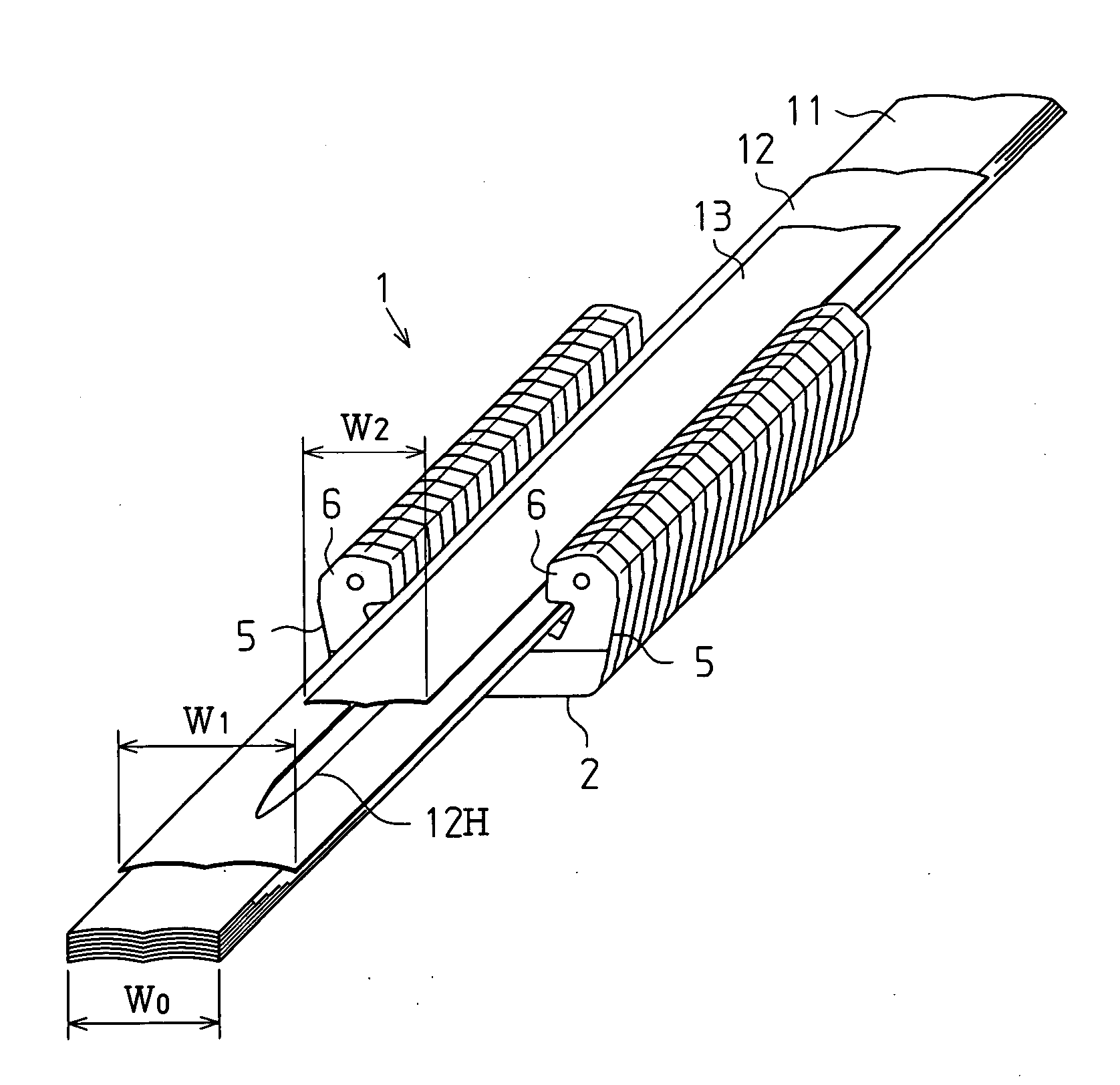
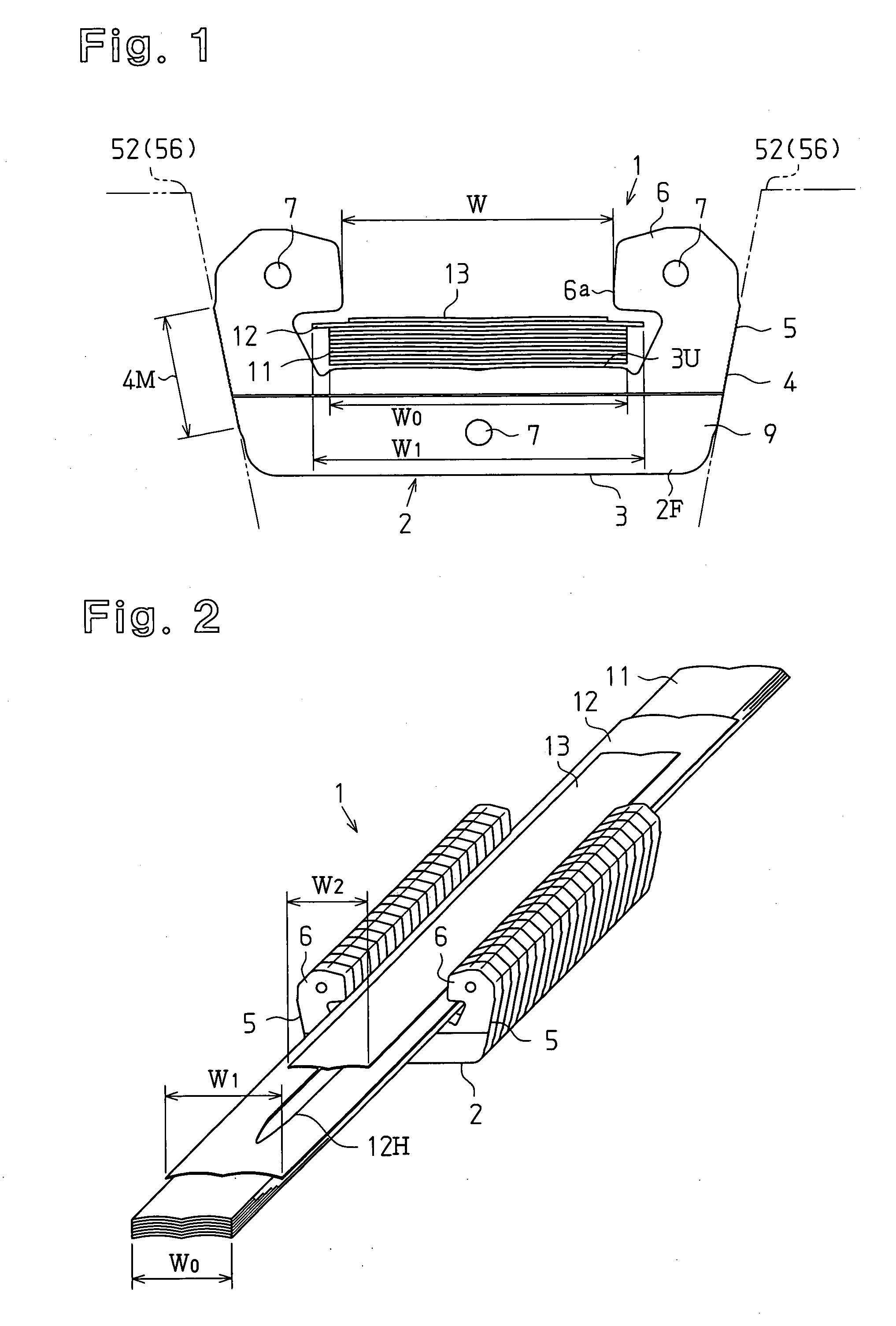
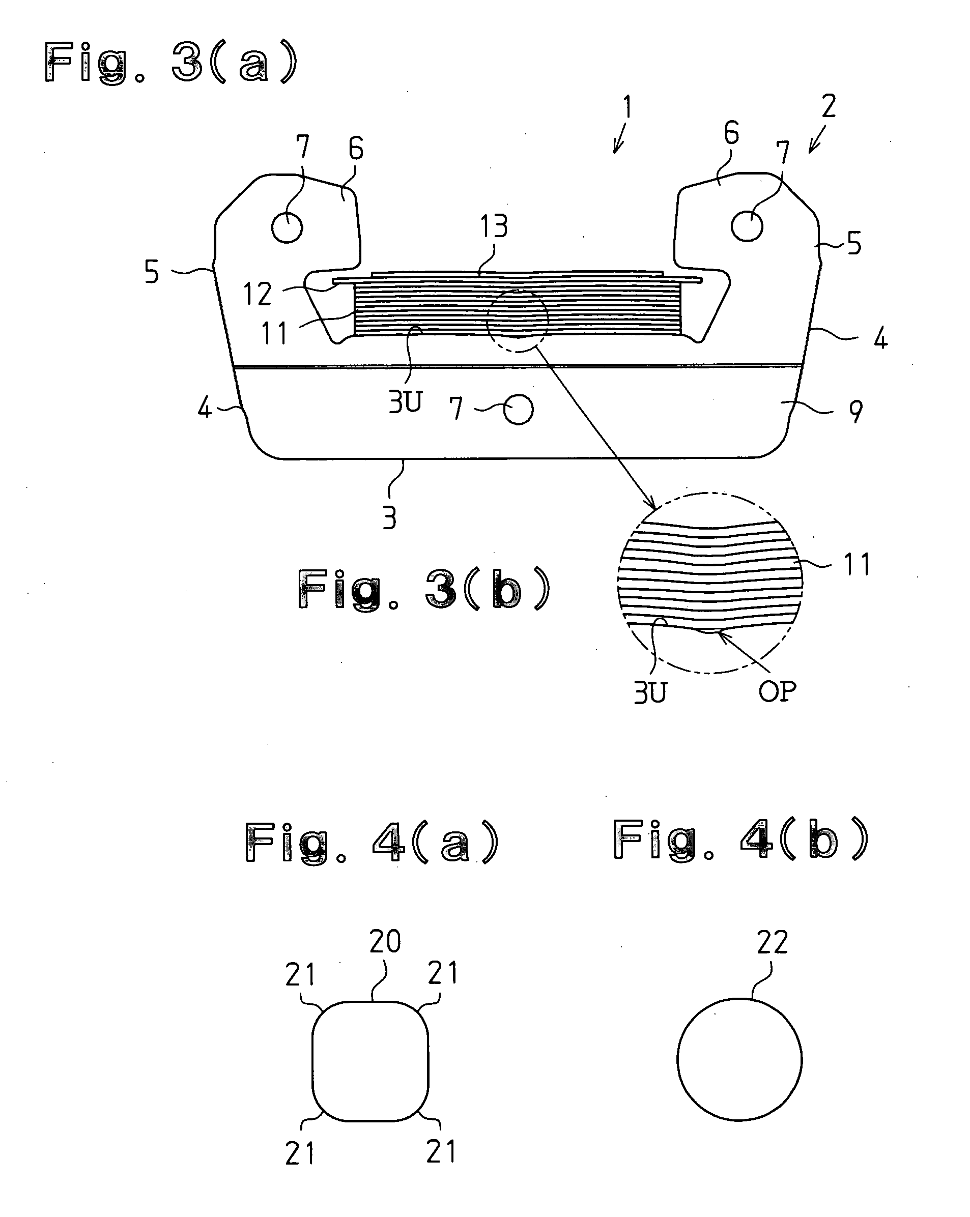
[0062] As shown in FIG. 1, a metallic belt 1 of the present invention includes a plurality of push blocks 2, a plurality of bands 11, a retainer 12, and a ring 13 for suppressing deformation of the retainer 12. The push block 2 is manufactured from a single wire material 20 having a square cross-sectional shape with corners 21 chamfered to be arcuate, as shown in FIG. 4(a). A wire material 22, such as that shown in FIG. 4(b), may also be used in place of the wire material 20.

[0063] When manufacturing the push block, the wire material 20 is first cut to a desired length, and bent. A bent product 2M is indicated by the broken lines shown in FIG. 5. The bent product 2M is then pressed to form the push block 2 indicated by the solid lines shown in FIG. 5. The push block 2 includes a body 3, a pair of pillars 5, and a pair of hoo...

second embodiment

[0094] In the push block 2 of a second modification shown in FIG. 25(c), the front half 4b of the side contact surface 4 forms and obtuse angle θ relative to the front surface 2F of the push block 2, and the rear half 4b of the side contact surface 4 forms an obtuse angle θ relative to the rear surface 2B of the push block 2. Accordingly, the ridge line 4a, for breaking up the oil film, extends along the entire length of the side contact surface 4 at the center of the side contact surface 4 in the widthwise direction. The ridge line 4a of the second modification has a function similar to the ridge line 4a of the push block 2 of the

[0095] In the push block 2 of a third modification shown in FIGS. 25(d) and 26(b), a step β extending along the entire length of the side contact surface 4 is provided at the front of the side contact surface 4. The ridge line 4a formed by the step β is located rearward from the center of the width 4W of the side contact surface 4. The oil film is broken u...

third embodiment

[0115] A steel plate may be used in place of the metal wire material to fabricate the push block 2 of the Since the push blocks actually used presently in the world are made of 100% steel, when using steel plates, there should be no resistance to the handling and such push block would become popular faster.

[0116] The ring forming the second retainer in the present embodiment may be omitted, and one type of retainer may be used for both the first and second retainers.


PUM


Abstract

A single-band type metallic belt wound between annular V-grooves of a drive pulley and a driven pulley is provided. The metallic belt includes a metal endless band having at least one layer, and a plurality of metal push blocks engaged and superimposed on the band in a manner enabling sliding in a longitudinal direction of the band. The push block includes a body formed by bending a single wire material and subsequently performing pressing so as to have two outer side surfaces defining side contact surfaces that are inclined to respectively make frictional contact with two inner surfaces of the annular V-grooves. A pair of pillars respectively extend along extensions of the two contact surfaces of the body and have an outer surface that is continuous with the side contact surfaces of the body. A pair of opposed hooks extend. The outer side surface of the push block that makes frictional contact with the V-grooves include an oil film breaking portion. An opening is defined by the pair of hooks, and a band holding surface is formed on the body in the opening. The band is inserted in the opening of each push block and held on the band holding surface. A metal retainer is arranged on an outer surface of the band in a manner engageable with the pair of hooks to ensure engagement between the band and the push blocks. A ring is attached to the outer surface of the retainer to prevent deformation of the retainer.

Description

FIELD OF THE INVENTION [0001] The present invention relates to an endless metallic belt wound between a drive pulley and a driven pulley, and a push block used therefor. BACKGROUND ART [0002] A metallic belt is used in, for example, continuously variable transmissions for automobiles or the like and includes at least a monolayer metal band, which is an endless belt, and a plurality of superimposed push blocks engaged with the endless belt in a manner enabling movement along the longitudinal direction of the band. Each push block includes a body, which comes into frictional contact with an inner surface of an annular V-shaped grooves in a drive pulley and driven pulley, and a head, which is arranged on a pillar extending from the middle of the body. A pair of band insertion grooves are provided on the left and right sides of the pillar. Such type of a metallic belt is generally referred to as a two-band belt. [0003] Each push block, which is manufactured by blanking a metal plate, is...

Claims


Application Information

Patent Timeline
IPC IPC(8): F16G5/16F16G1/21
CPCF16G5/16F16G5/163F16H9/24
Inventor TAKAGI, SHIGEMASATAKAGI, YUTAKA
Owner FUKUJU INDS
Why Eureka
Try Eureka