Novel gantry machining center

A processing center and gantry technology, applied in metal processing equipment, metal processing machinery parts, manufacturing tools, etc., can solve the problems of assembly difficulty, guide surface drop, affecting processing accuracy and processing strength, etc., to ensure rigidity and strength, prevent Assembly errors, the effect of simplifying assembly operations

Inactive Publication Date: 2014-03-12
NANTONG GUOSHENG INTELLIGENCE TECH GRP CO LTD
View PDF7 Cites 9 Cited by
  • Summary
  • Abstract
  • Description
  • Claims
  • Application Information

AI Technical Summary

Problems solved by technology

[0002] There are many defects in the structure of the gantry machining centers currently on the market. For example, the composition of a beam and two columns is usually a split structure. During on-site assembly, each gantry component requires high precision during processing and a long production cycle. , which increases the production cost and brings difficulty to assembly; in addition, the rigidity and strength of the split-type gantry support are poor, which affects the machining accuracy and strength, and cannot be used for strong cutting, thereby reducing production efficiency;
[0003] In addition, the main shaft of the gantry machining center is generally connected with the main shaft motor by a belt, and the main shaft motor is arranged outside the main shaft box. This structure has the following problems: the main shaft motor bracket is installed on the ram, and the main shaft motor is installed on the main shaft motor bracket. The motor and the main shaft are connected, because there is a certain distance between the motor and the main shaft, the rigidity is not good, and the torque of the motor cannot be fully exerted, because the belt drive can only exert 60% of the motor torque
The spindle motor is installed at the front end of the spindle box, which is not easy to process deep cavity molds
[0004] The general gantry machining centers are designed with two Y guide rails, which are generally designed on the front side of the beam. Such a structural design has the following problems: the two Y guide rails are all in front, and can only bear one Direction of stress, while there is a certain drop in the guide surface, the entire cross-sectional size of the beam is reduced, and the rigidity of the entire gantry machining center equipment becomes poor
[0005] The sliding seat of the gantry machining center in the prior art is generally an integral structure, that is, the sliding seat and the base are formed at one time. This integral structure mainly has the following problems: 1. The mold is large in shape and difficult to manufacture; 2. The size of the upper end is small. It is easy to produce deformation and casting cracks; 3. The volume is too high during transportation, it is not easy to disassemble, and the transportation cost is high

Method used


Image

  • Novel gantry machining center
  • Novel gantry machining center
  • Novel gantry machining center

Examples


Embodiment

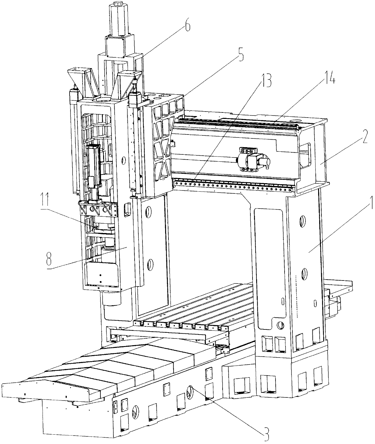
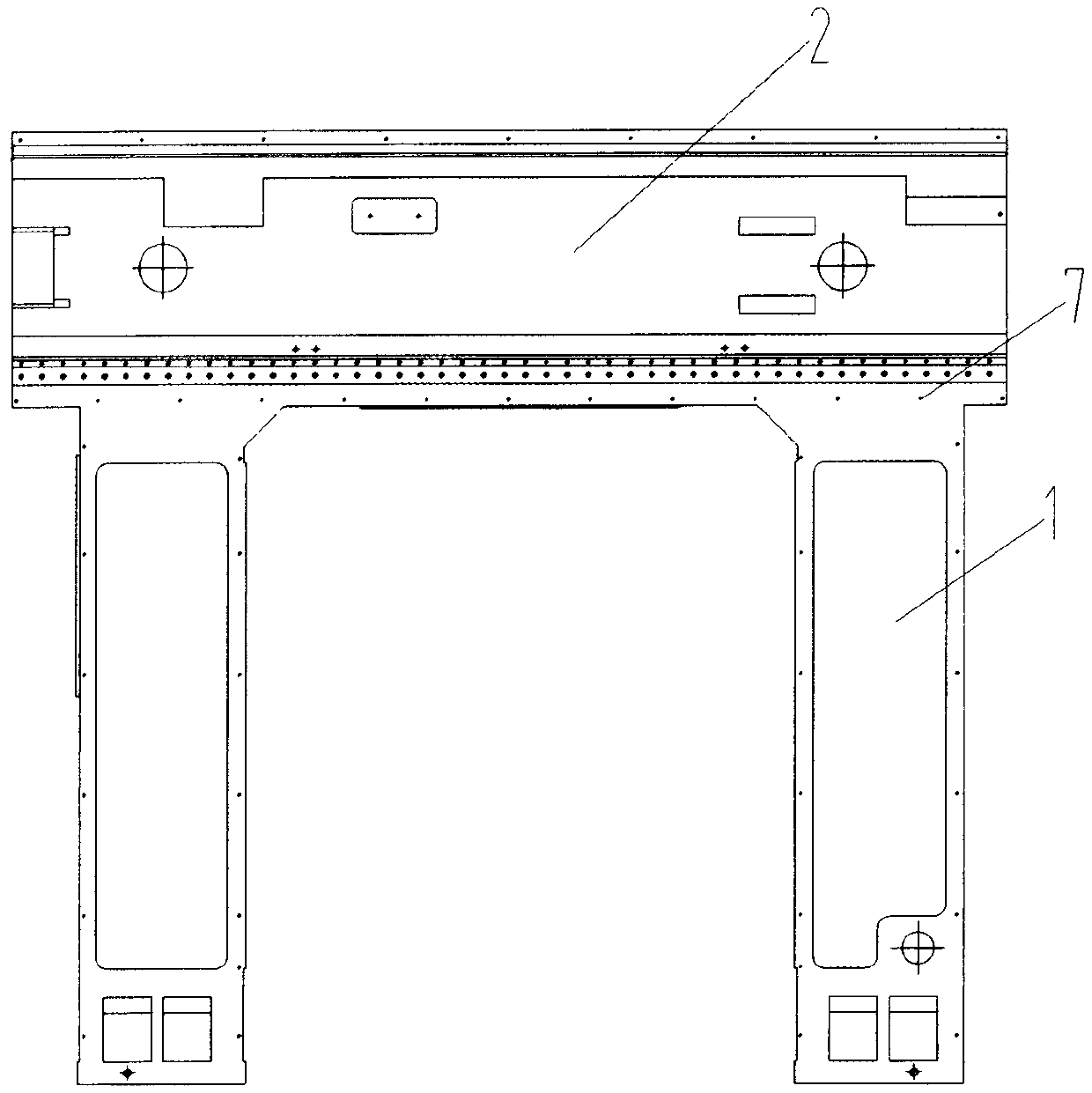
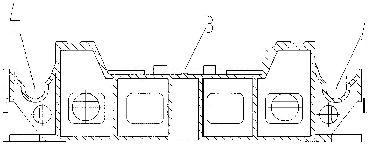
[0031] Such as figure 1 Shown: a new type of gantry machining center, including column 1, beam 2, bed body 3, casting chip conveyor groove 4, slide body 5 and slide bracket 6, etc., characterized in that the column and beam are The cast iron one-time molding integral structure; the casting chip conveyor groove 4 is arranged on both sides of the bed body 3, and the bed body 3 is an integral structure of casting one-time molding; the slide body 5 and the slide bracket 6 It is a split structure, fixed together by bolts.

[0032] As one of the preferred solutions, a stiffener plate 7 is provided inside the connection between the column 1 and the beam 2 .

[0033] As one of the preferred solutions, the connecting portion of the casting chip conveyor groove 4 and the bed body 3 is a slope surface, and the angle between the slope surface and the edge of the bed body 3 in the vertical direction is 20-40°.

[0034] As one of the preferred solutions, it also includes a spindle box 8, ...


PUM


Abstract

The invention discloses a novel gantry machining center which comprises a stand column, a beam, a lathe bed body, casting chip removal device grooves, a sliding base body, a sliding base support and the like. The novel gantry machining center is characterized in that the stand column and the beam are of an integrated structure which is one-time formed by cast iron, the casting chip removal device grooves are formed in the two sides of the lathe bed body, the casting chip removal device grooves and the lathe bed body are of an integrated structure which is one-time formed by castings, the sliding base body and the sliding base support are of a split structure and are fixedly connected together through bolts. According to the novel gantry machining center, the partial integrated structure or the split structure is adopted, the rigidity and strength of the whole gantry machining center are improved, and assembling efficiency and production efficiency are improved.

Description

technical field [0001] The invention belongs to the field of machine tool processing machinery, and in particular relates to a novel gantry processing center. Background technique [0002] There are many defects in the structure of the gantry machining centers currently on the market. For example, the composition of a beam and two columns is usually a split structure. During on-site assembly, each gantry component requires high precision during processing and a long production cycle. , which increases the production cost and brings difficulty to assembly; in addition, the rigidity and strength of the split-type gantry support are poor, which affects the machining accuracy and strength, and cannot be used for strong cutting, thereby reducing production efficiency; [0003] In addition, the main shaft of the gantry machining center is generally connected with the main shaft motor by a belt, and the main shaft motor is arranged outside the main shaft box. This structure has the...

Claims


Application Information

Patent Timeline
Patent Type & Authority Applications(China)
IPC IPC(8): B23Q1/01B23Q11/00B23B19/00
CPCB23Q1/25B23Q1/012B23Q1/015B23Q1/017B23Q1/70B23Q5/10B23Q11/0067
Inventor 潘卫国崔德友任东缪申徐新朋商爱坤刘传进汪建丽蒋小飞
Owner NANTONG GUOSHENG INTELLIGENCE TECH GRP CO LTD
Why Eureka
Try Eureka