Operating machine

a technology of operating machine and operating frame, which is applied in the direction of tractors, roofs, transportation and packaging, etc., can solve the problems of deterioration in strength of transverse plate, disruption of strength balance, and needing time and effort, and achieve excellent efficiency in installation or removal, ensuring strength and rigidity of an upper frame.

Inactive Publication Date: 2014-09-02
KOBELCO CONSTR MASCH CO LTD
View PDF7 Cites 4 Cited by
  • Summary
  • Abstract
  • Description
  • Claims
  • Application Information

AI Technical Summary

Benefits of technology

[0011]It is an object of the present invention to provide an operating machine capable of attaining excellent efficiency in installation or removal of a line member, while ensuring strength and rigidity of an upper frame.

Problems solved by technology

In this situation, if the line member is routed to largely avoid the transverse plate, or arranged to stride over the transverse plate, layout of the line member becomes disorderly, which gives rise to a need to take time and effort for installation or removal of the line member, and is more likely to lead to a trouble such as wrong interconnection.
However, when a hole is made in the transverse plate, a transverse cross-sectional area of the transverse plate is reduced by an opening area of the hole, and stress is likely to concentrate on a region around the hole, causing deterioration in strength of the transverse plate.
Consequently, balance in strength is disrupted, which is likely to lead to deterioration in strength and rigidity of an upper frame.
Moreover, during installation or removal of the line member, it is necessary to lead or pull an elongate line member into / out from the hole all the time, so that there is a disadvantage that operation (installation / removal) efficiency becomes worse.

Method used


Image

  • Operating machine
  • Operating machine
  • Operating machine

Examples


first modification

[0061](First Modification)

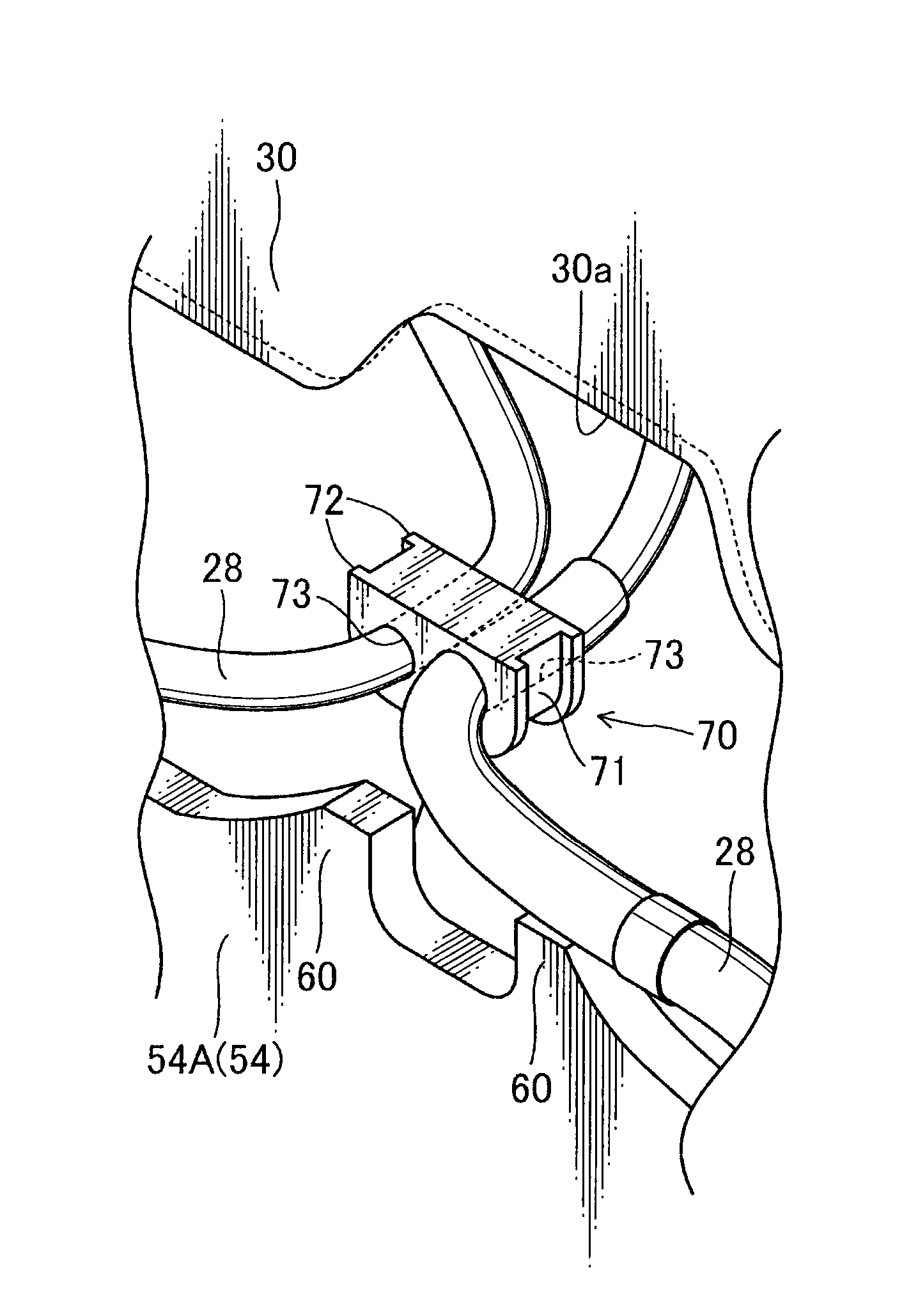
[0062]FIGS. 8 and 9 illustrate examples of a first modification of the above embodiment. The above embodiment has been described based on an example in which two line members 28 are set to pass through between the pair of protrusions 60. However, the number, arrangement and each shape (size) of line members 28 to be set to pass through between the protrusions 60 may be appropriately changed according to specifications. Further, in conformity to the number, arrangement and each shape (size) of line members 28 to be set to pass through between the protrusions 60, the arrangement and each shape of the protrusions 60 and the shape of the grommet 70 may be appropriately changed.

[0063]For example, as illustrated in FIG. 8, each of the protrusions 60 may be formed in a vertically long shape, and a vertically-long grommet 70 formed with a plurality of through-holes 73 arranged side-by-side in a vertical multi-stage manner may be attached between the protrusions 60....

second modification

[0064](Second Modification)

[0065]FIGS. 10 and 11 illustrate examples of a second modification of the above embodiment. The above embodiment has been described based on an example in which the protrusions 60 are integrally formed with the partitioning transverse plate 54A. However, the protrusions 60 may be composed of a member separate from the partitioning transverse plate 54A, and attached to the partitioning transverse plate 54A. In this case, it becomes possible to easily change a shape, etc., of the protrusions 60 to provide enhanced versatility, and eliminate the risk of impairing original strength and rigidity of the partitioning transverse plate 54A.

[0066]For example, as illustrated in FIGS. 10 and 11, a joinable piece 80 may be formed using a metal plate, in such a manner that the joinable piece 80 has a pair of protruding portions 80a corresponding to the pair of protrusions 60 in the above embodiment, and a base portion 80b provided integrally with the protruding portions...


PUM


Abstract

An operating machine comprises a machine body mounted on a lower propelling body. The machine body comprises an upper frame, and a line member mutually connecting a plurality of devices installed to the upper frame. The upper frame has a bottom plate, a pair of longitudinal plates each provided to stand on the bottom plate and extend in a front-rear direction, while being disposed in spaced-apart relation to each other in a right-left direction, and a transverse plate provided to stand on the bottom plate and extend in the right-left direction, while being joined to each of the longitudinal plates. A specific plate consisting of at least one of the pair of longitudinal plates and the transverse plate has an upper edge on which a pair of protrusions are provided in opposed relation to each other, and the line member is set to pass through between the pair of protrusions.

Description

BACKGROUND OF THE INVENTION[0001]1. Field of the Invention[0002]The present invention relates to an operating machine such as a hydraulic shovel or a crane.[0003]2. Background Art[0004]Most operating machines are configured such that a machine body for performing working operations is mounted on a crawler-type or wheel-type lower propelling body. For example, as for a hydraulic shovel, an upper frame is slewably mounted on a lower propelling body, and various components, such as an equipment room in which an engine and hydraulic devices are housed, a cabin designed to allow an operator to ride thereon and perform various manipulations, a working implement comprising a boom, an arm and a bucket each adapted to be moved according to a manipulation by the operator, and a counterweight for keeping front-rear balance with respect to the working implement, are installed on the upper frame.[0005]As above, such heavy devices are installed on the upper frame, and a load change caused by trav...

Claims


Application Information

Patent Timeline
Patent Type & Authority Patents(United States)
IPC IPC(8): E02F9/10E02F9/08E02F9/22
CPCE02F9/0816E02F9/2275A01G23/08E02F3/325
Inventor USHIROGUCHI, ASUKA
Owner KOBELCO CONSTR MASCH CO LTD
Why Eureka
Try Eureka