Suspension of vehicle

a suspension and vehicle technology, applied in the direction of resilient suspensions, vehicle components, interconnection systems, etc., can solve the problems of improper adjustment of the alignment-change characteristics of the suspension, improper adjustment of the rigidity of the curve portion of the torsion beam, so as to ensure the rigidity and productivity, and the vehicle floor level is low

Active Publication Date: 2015-09-15
MAZDA MOTOR CORP
View PDF15 Cites 4 Cited by
  • Summary
  • Abstract
  • Description
  • Claims
  • Application Information

AI Technical Summary

Benefits of technology

[0010]An object of the present invention is to provide a suspension of a vehicle which can properly ensure the rigidity and the productivity, attaining low floor-level of the vehicle.
[0012]In the present suspension of the vehicle, since the torsion beam is configured in the arch shape such that its central portion projects forward and upward in the slant shape and is located above the level of the wheel center, some space can be ensured below the torsion beam, and also the rigidity can be improved properly because any stress concentration portion which may be caused by crossing of the axial center of the torsion beam over the longitudinal direction of the torsion beam is not formed. Further, since the torsion beam is comprised of the open cross-section member which includes the arch lower-half portion and the arch upper-half portion, the rear end portion of the arch lower-half portion being formed integrally with the rear end portion of the upper-half portion, and the sectional shape of the arch lower-half portion in the cross section perpendicular to the longitudinal direction of the arch lower-half portion is configured to be substantially horizontal when the vehicle is in the standard state, and the central portion, in the vehicle width direction, of the torsion beam is configured such that the front edge portion of the arch lower-half portion and the front edge portion of the arch upper-half portion are located substantially at the same position in the vehicle longitudinal direction when the vehicle is in the full-rebound state, the floor panel can be located at a lower level by the amount of closing deformation of the open cross-section in the vehicle's full-rebound state, by utilizing closing deformation of the open cross-section formed by the arch upper-half portion and the arch lower-half portion which occurs because of absorption of the torsional load. Moreover, since the sectional shape of the arch lower-half portion is configured to be substantially horizontal when the vehicle is in the standard state and be in a slant shape such that its front is located at a lower level than its rear when the vehicle is in the full-rebound state, it can be prevented that water or the like stay inside the open cross-section of the torsion beam, so that any hole for draining such water or the like can be omitted, therefore the productivity of the torsion beam can be improved improperly.
[0013]According to an embodiment of the present invention, the vehicle is provided with a rear-wheel drive device which is arranged at a vehicle-body rear portion and a propeller shaft which is connected to the rear-wheel drive device via a connection portion and extends in the vehicle longitudinal direction, and the propeller shaft is arranged to pass through a space formed below the torsion beam. Thereby, any interference of the torsion beam with the propeller shaft can be prevented properly, so that this suspension is applicable to the vehicle provided with the rear wheels as a driving wheel.
[0014]According to another embodiment of the present invention, the torsion beam is configured such that a rear end portion thereof is located at a position near and above the connection portion when the vehicle is in the full-rebound state. Thereby, any interference of the torsion beam with the rear-wheel drive device including the connection portion in the vehicle's full-rebound state can be prevented properly.
[0015]According to another embodiment of the present invention, the torsion beam is configured such that the central portion, in the vehicle width direction, of the arch upper-half portion is located at a position near and below a seat-cushion attachment portion formed at the floor panel when the vehicle is in the full-rebound state. Thereby, any interference of the torsion beam with the seat-cushion attachment portion which is located near the torsion beam and at the lowest level of the floor panel can be prevented properly.

Problems solved by technology

Therefore, in a case in which the central portion, in the vehicle width direction, of the torsion beam B curves upward, the shear center C also moves upward according to this curving of the torsion beam B. Consequently, there occurs a problem in that the alignment-change characteristics of the suspension may change improperly.
In general, a long member, such as the torsion beam, has a tendency that in a case in which it has a bending portion at some point in its longitudinal direction, a cross-section crumbling happens to this bending portion of the long member, so that the rigidity decreases.
Therefore, there is a problem in that if the upward curve portion is formed at the central portion, in the vehicle width direction, of the torsion beam, the rigidity of the curve portion of the torsion beam may decrease improperly, so that the vehicle may be inferior in the maneuverability and stability.
However, the suspension of the first patent document has a problem in that the productivity of the torsion beam may deteriorate.
That is, since the torsion-beam type of suspension is configured such that the open cross-section formed by the one-side half portion and the other-side half portion which respectively extend in the longitudinal direction of the torsion beam opens upward, there is a concern that water or the like splashed by the wheels may stay inside the open cross-section of the torsion beam.
In a case in which the crushed pipe type of torsion beam disclosed in the above-described third patent document is used, it may be necessary that anti-rusting treatment or the like are applied to the hollow portion, so that forming of such drain holes may become uneasy.
However, the suspension of the second patent document may not be sufficient in rigidity improvement of the torsion beam.
Thus, the suspension of the first patent document may have the same problem.
However, since the suspensions of the above-described first or second patent documents have the upward-curve portion at the central portion, in the vehicle width direction, of the torsion beam and therefore this upward-curve portion possibly interferes with the floor panel when the vehicle is in the full-rebound state, there is a concern that the floor of the vehicle may not be positioned at a sufficiently low level.

Method used


Image

  • Suspension of vehicle
  • Suspension of vehicle
  • Suspension of vehicle

Examples


Embodiment Construction

[0027]Hereinafter, an embodiment of the present invention will be described specifically referring to the accompanying drawings. The following descriptions merely exemplify the present invention substantially, so the present invention and its applications or uses should not be limited by the descriptions.

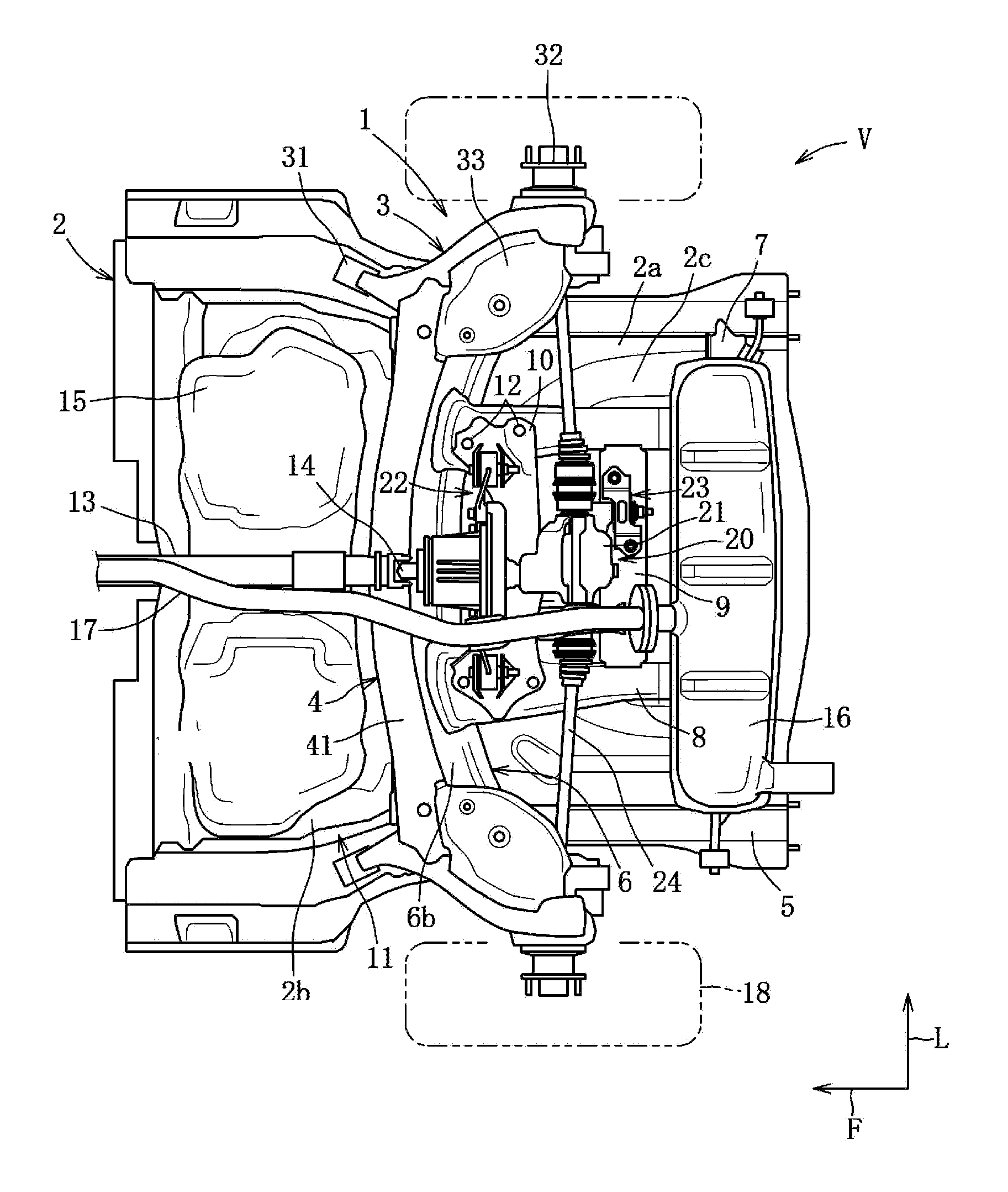
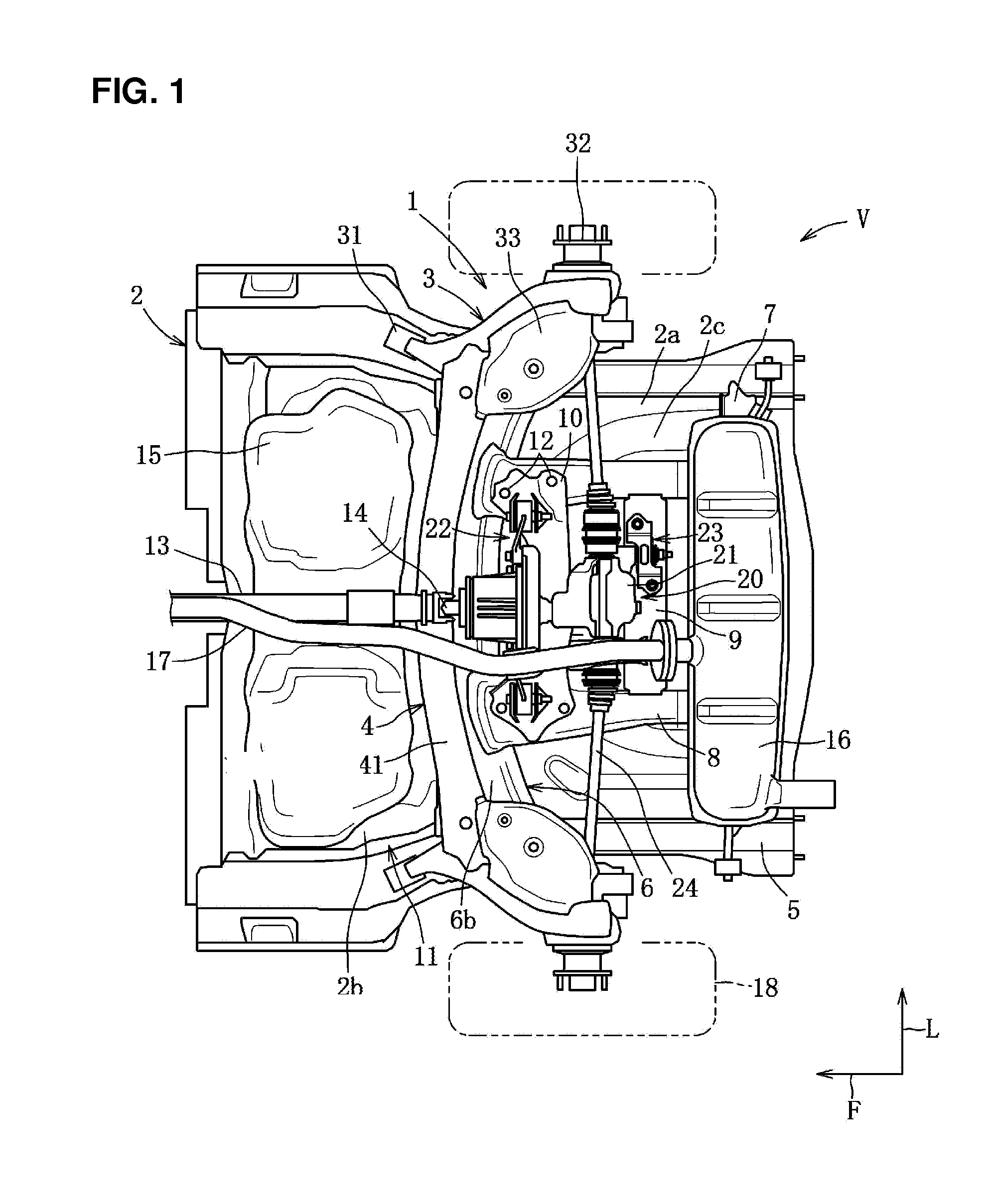
[0028]A suspension 1 of a vehicle V according to the present embodiment comprises, as shown in FIG. 1, a pair of right-and-left trailing arms 3 which are pivotally supported at a vehicle body below a floor pane 2 at their front end portions and rotatably support a pair of wheels 18 at their rear end portions, a torsion beam 4 which extends in a vehicle width direction and is connected to the pair of right-and-left trailing arms 3 at its both end portions, and others. In the figures, an arrow F shows a forward direction and an arrow L shows a left direction.

[0029]First, a rear portion of a vehicle body at which the suspension 1 of the vehicle V is supported will be described briefly....


PUM


Abstract

A torsion beam is configured in an arch shape and comprised of an open cross-section member including an arch lower-half portion and an arch upper-half portion. A sectional shape of the arch lower-half portion in a cross section perpendicular to a longitudinal direction of the arch lower-half portion is configured to be substantially horizontal when a vehicle is in a standard state, and a central portion, in the vehicle width direction, of the torsion beam is configured such that a front edge portion of the arch lower-half portion and a front edge portion of the arch upper-half portion are located substantially at the same position in a vehicle longitudinal direction when the vehicle is in a full-rebound state. Thereby, the rigidity and the productivity can be endured, attaining low floor-level of the vehicle.

Description

BACKGROUND OF THE INVENTION[0001]The present invention relates to a suspension of a vehicle, and in particular relates to a torsion-beam type of suspension provided with a torsion beam which is connected to a pair of right-and-left trailing arms.[0002]Conventionally, a torsion-beam type of suspension, which comprises a pair of right-and-left trailing arms, front end portions of which are pivotally supported at a vehicle body below a floor panel and rear end portions of which rotatably support a pair of right-and-left wheels and a torsion beam extending in a vehicle width direction, both end portions, in the vehicle width direction, of which are connected to the pair of right-and-left trailing arms, is known. In the torsion-beam type of suspension, the torsion beam which is comprised of an open cross-section member which includes a pair of half portions (a one-side half portion and an other-side half portion) extending in its longitudinal direction and has a U-shaped cross section or...

Claims


Application Information

Patent Timeline
Patent Type & Authority Patents(United States)
IPC IPC(8): B60G3/12B60G21/05
CPCB60G21/052B60G21/051B60G2200/23B60G2206/20
Inventor AKAKI, HIROYUKINISHI, TAKASHIKUSAKA, YUKITANAKA, HIROSHIMANABE, TOSHIYUKI
Owner MAZDA MOTOR CORP
Why Eureka
Try Eureka