

Radial roller bearing cage
A roller bearing and cage technology, applied in the field of cages for radial roller bearings, can solve the problems of increasing the number and increasing the manufacturing cost, and achieve the effects of improving work efficiency, preventing fretting wear and reducing volume
- Summary
- Abstract
- Description
- Claims
- Application Information
AI Technical Summary
Problems solved by technology
Method used
Image

Examples
Embodiment Construction
[0064] [the first example of embodiment]
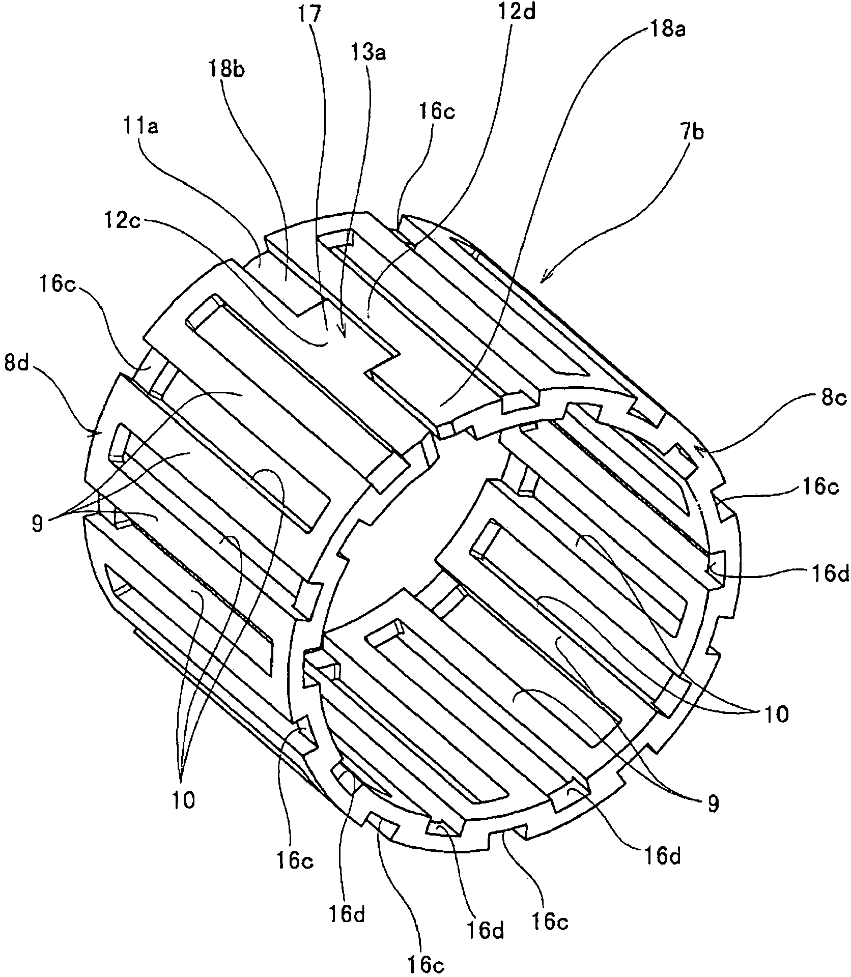
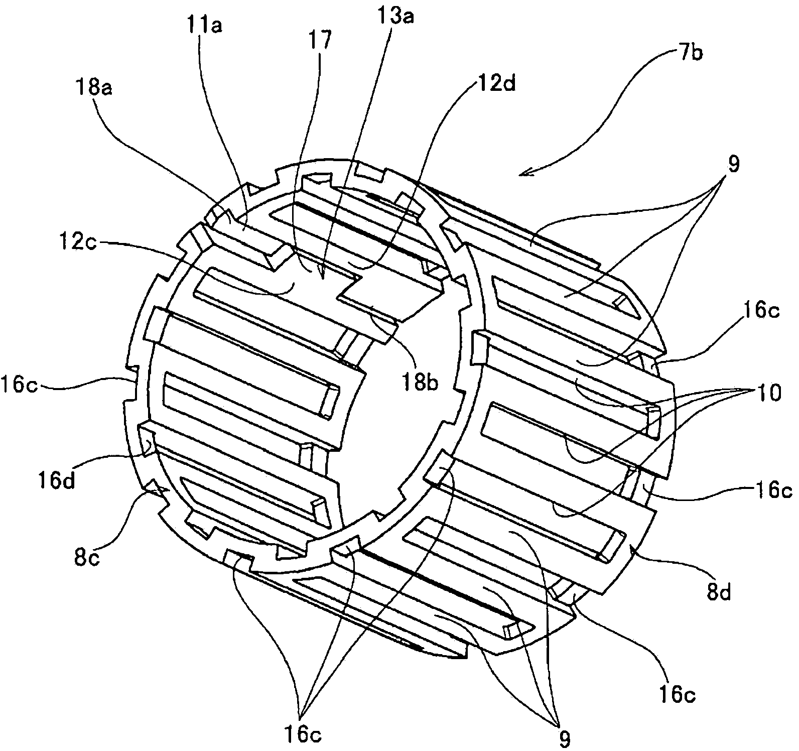
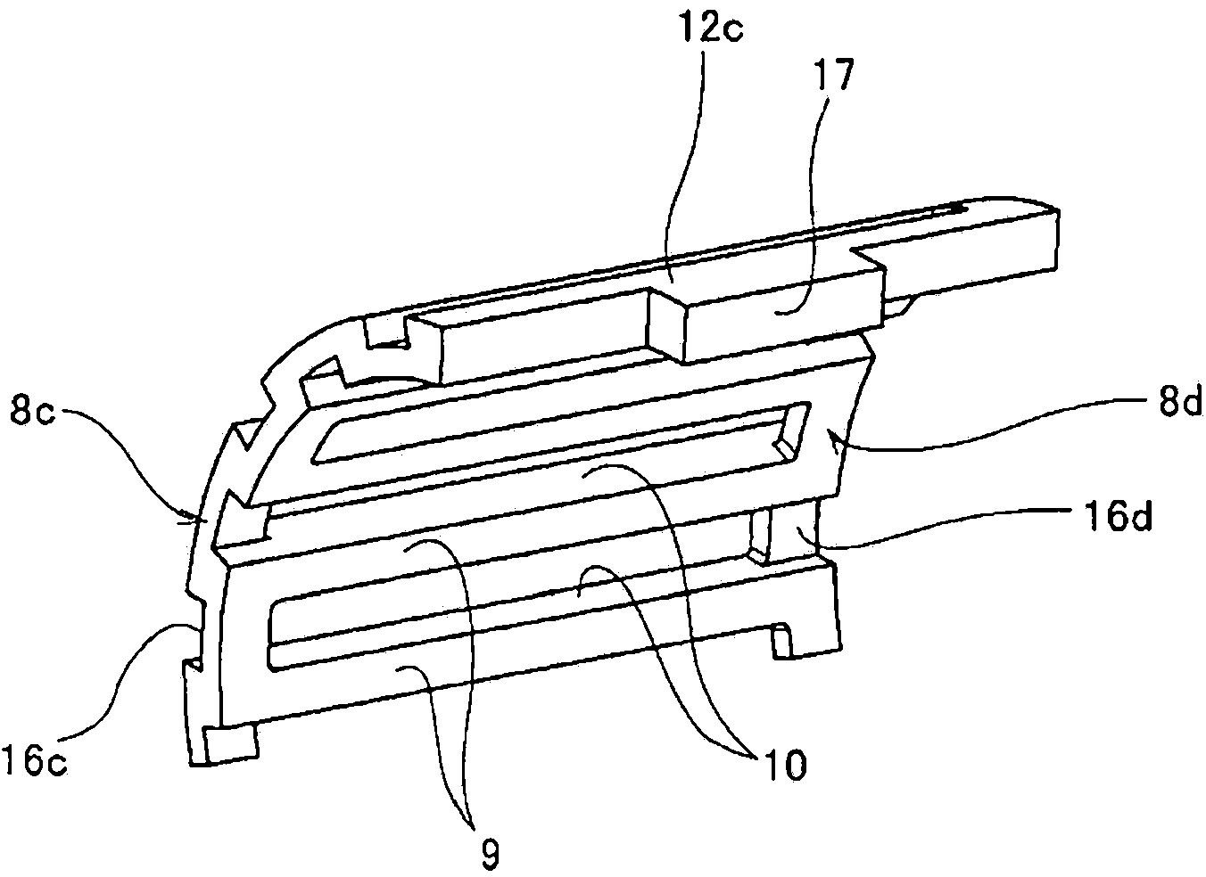
[0065] Figure 1 ~ Figure 4 This is the first example showing the embodiment of the present invention. The radial roller (needle) bearing cage 7b of this example is provided with a pair of ring-shaped rim portions 8c and 8d which are arranged concentrically with each other at intervals in the axial direction, and are intermittently spaced throughout the circumferential direction. The plurality of column parts 9 are provided in a state of being bridged between these rim parts 8c and 8d. Moreover, each of the four-sided portions surrounded by the adjacent column portion 9 in the circumferential direction and the rim portions 8c, 8d is made to freely hold the roller 6 for rolling (see Figure 23 ) pocket 10.
[0066] On the peripheral surfaces of the rim portions 8c, 8d, the portions matching the pockets 10 in the axial direction are alternately formed in the circumferential direction, and concave portions dented inward in the radial d...
PUM
 Abstract
Description
Claims
Application Information