Sonic monitor system for a tank

Active Publication Date: 2016-01-14
HUSKY
View PDF18 Cites 8 Cited by
  • Summary
  • Abstract
  • Description
  • Claims
  • Application Information

AI Technical Summary

Benefits of technology

[0023]The present disclosure provides a sonic monitor system for a tank that can be easily employed with highly reliable results to prevent spilling of gasoline or other liquid from a storage tank.
[0024]The pr

Problems solved by technology

However, such gauges do not provide any warning or indication as to when the contents of the tank reac

Method used


Image

  • Sonic monitor system for a tank
  • Sonic monitor system for a tank
  • Sonic monitor system for a tank

Examples


Example

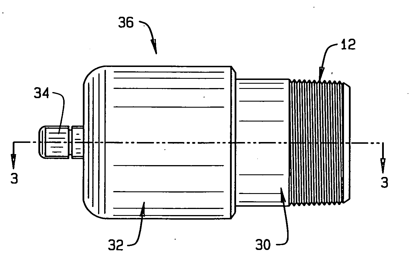
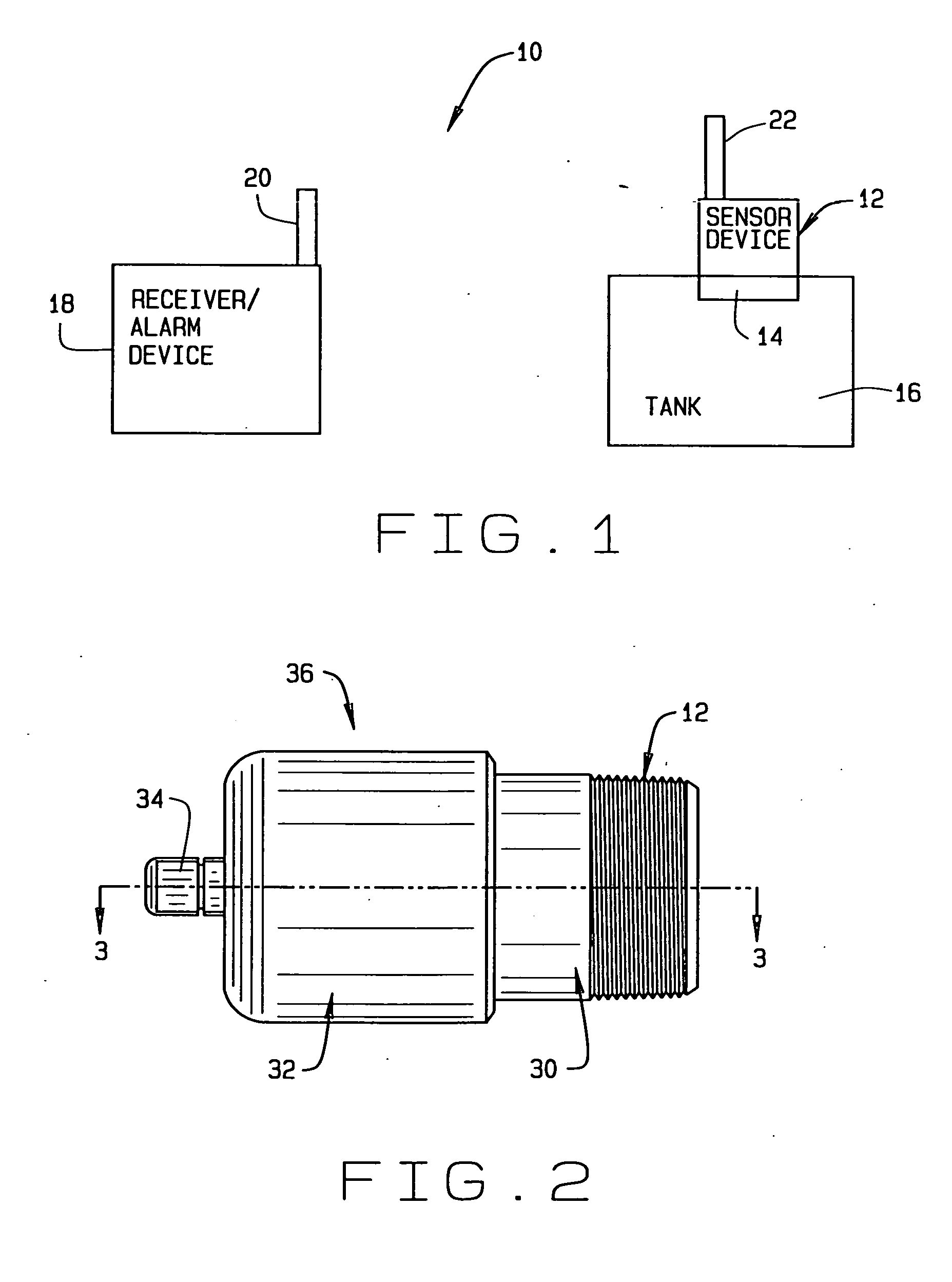
[0041]Referring now to the drawings, wherein like numbers refer to like items, number 10 identifies a preferred embodiment of a sonic monitor system for a tank constructed according to the present disclosure. With reference now to FIG. 1, the sonic monitor system for a tank 10 is shown comprising a remote tank sensor device 12 being installed in a bung or other opening 14 of a storage tank 16 and a receiver device 18. The receiver device 18 has an antenna 20 for transmitting and receiving signals to and from the remote tank sensor device 12. The remote tank sensor device 12 also has an antenna 22 for transmitting and receiving signals to and from the receiver device 18. The remote tank sensor device 12, as will be explained in detail herein, is capable of detecting or monitoring a level of fluid or liquid being stored within the tank 16. For example, the remote tank sensor device 12 may continuously or automatically send an ultrasonic signal into the tank 16 to gauge or determine th...


PUM


Abstract

A sonic monitor system for a tank is disclosed in which the system comprises a remote tank sensor device for installation in a bung opening of a storage tank for determining a level of fluid within the storage tank and for generating a signal indicative of the level of fluid within the storage tank, and a receiver device for receiving the signal indicative of the level of fluid within the storage tank, the receiver device having a display and a siren with the receiver device actuating the siren when the receiver device determines that the level of fluid within the tank is at a predetermined level.

Description

CROSS REFERENCE TO RELATED APPLICATION[0001]This nonprovisional patent application claims priority to the provisional application having Ser. No. 61 / 998,829, filed on Jul. 9, 2014.FIELD OF THE DISCLOSURE[0002]This disclosure generally relates to monitoring systems, and more particularly to a sonic monitor for determining a level of a fluid within a storage tank.BACKGROUND[0003]Storage tanks are used to store various fluids such as oil, waste oil, diesel fuel, antifreeze, and other fluids having a low flash point. These fluids are stored to be used at automotive repair facilities for various purposes. For example, motor oil is used during an engine oil change and antifreeze is used to refill a radiator. It is also possible that waste oil may be collected and used to provide fuel to a generator or a heater. The storage tank may have various threaded openings in the top of the tank. One of the openings may be a 2 inch diameter bung hole opening that is used to fill or empty the tank. A...

Claims


Application Information

Patent Timeline
IPC IPC(8): G01F23/296
CPCG01F23/296G01F23/2962
Inventor WIERSMA, ROGER E.GANDER, CHRISTOPHER D.
Owner HUSKY
Why Eureka
Try Eureka