
Plasma processing apparatus and method and apparatus for measuring DC potential

Inactive Publication Date: 2005-05-05
TOKYO ELECTRON LTD
View PDF9 Cites 34 Cited by
  • Summary
  • Abstract
  • Description
  • Claims
  • Application Information

AI Technical Summary

Benefits of technology

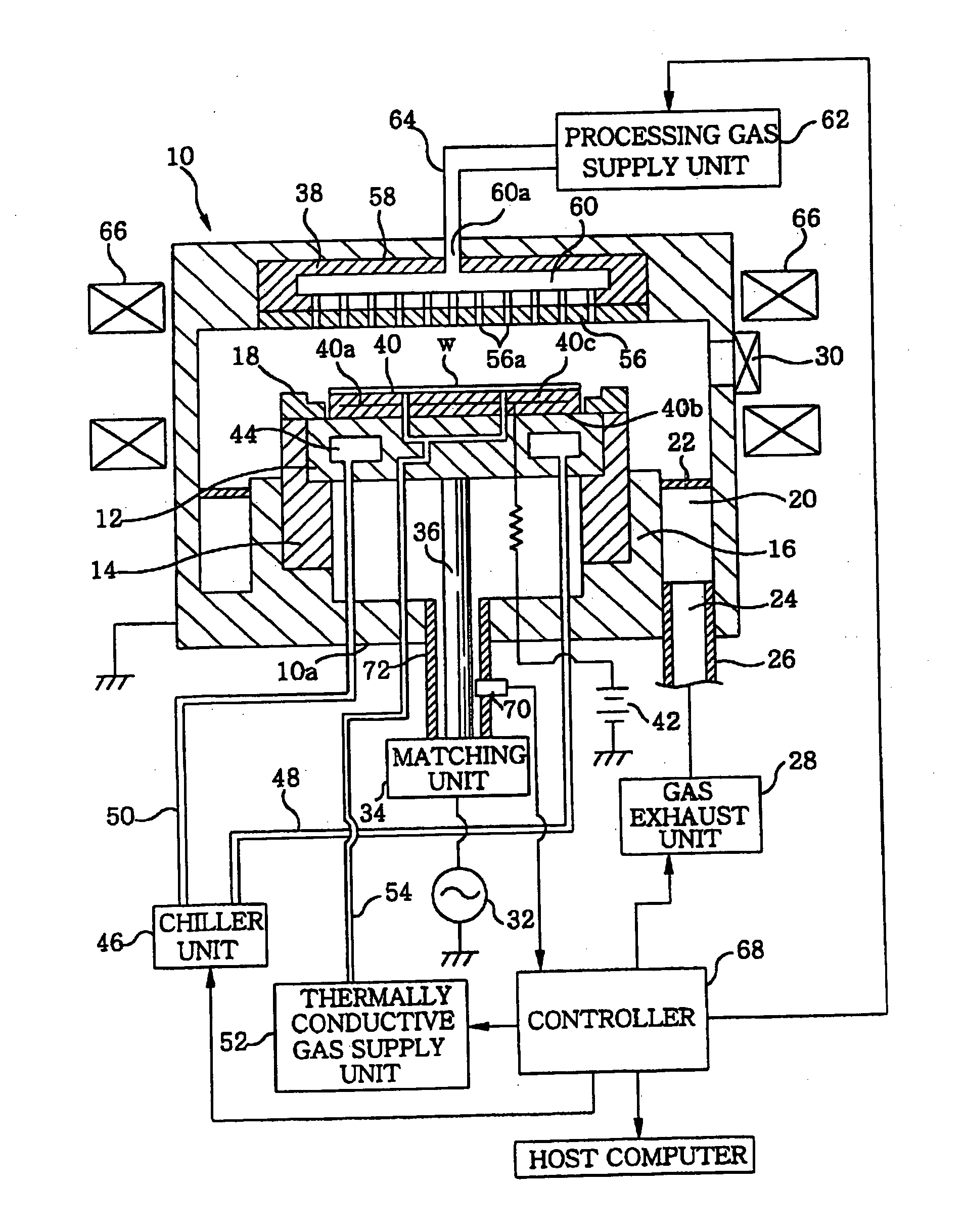
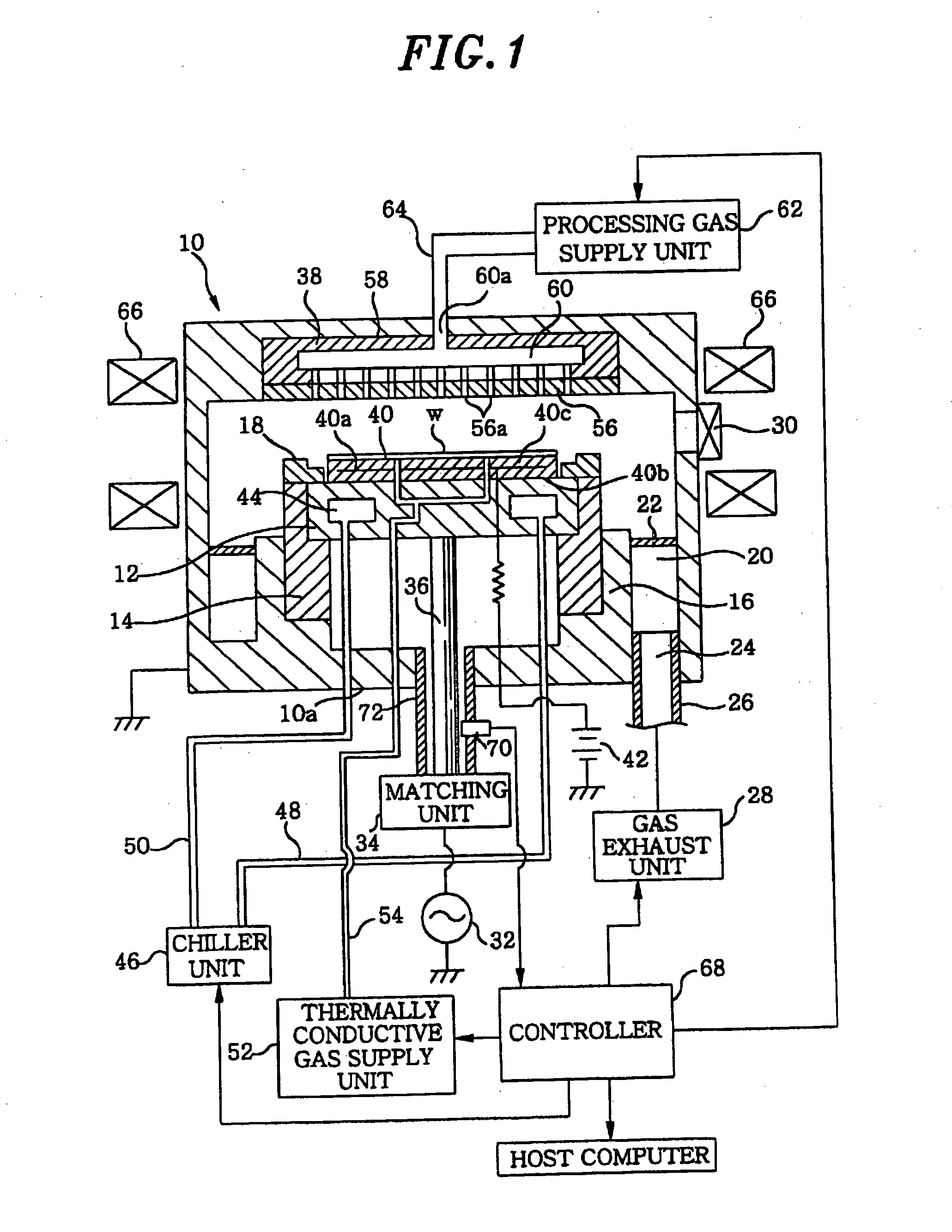
[0005] The present invention was conceived taking into consideration the problems of the conventional technology. It is, therefore, an object of the present invention to provide a DC potential measuring method, a DC potential measuring apparatus and a plasma processing, apparatus capable of safely and accurately measuring a DC potential of a member propagating or receiving a high frequency from a high frequency power supply.
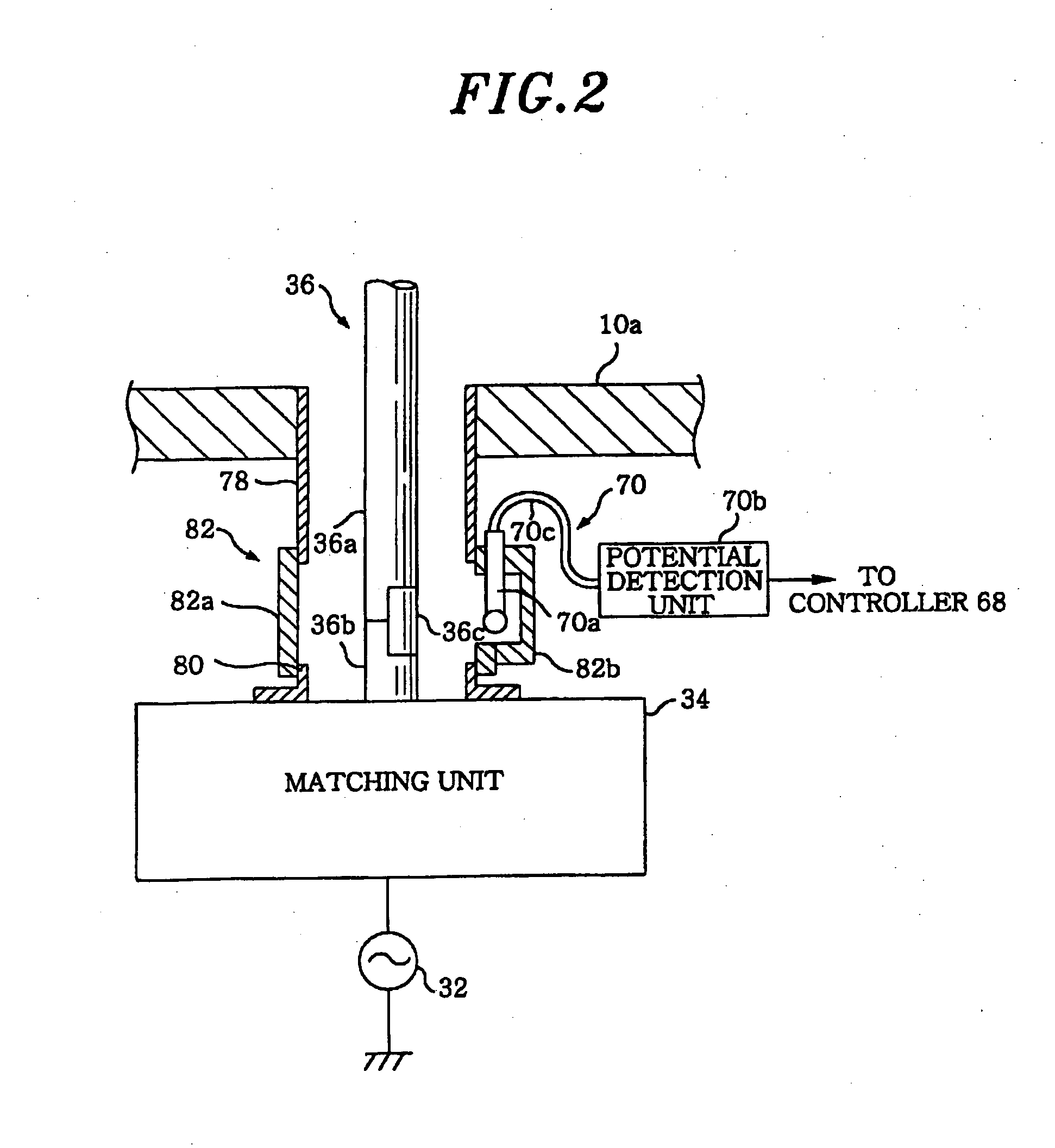
[0012] Furthermore, the high frequency feeding conductor may be preferably configured to include a first bar-type conductor whose one end is fixed to a rear surface of the first electrode; a second bar-type conductor whose one end is fixed to the output terminal of the matching unit; and a first connecting part for attachably and detachably connecting the other ends of the first and the second bar-type conductor with each other. The cylindrical conductor may also be preferably configured to include a first cylindrical conductor portion whose one end is coupled to the processing vessel; a second cylindrical conductor portion whose one end is coupled to the matching unit; and a second connecting part for attachably and detachably connecting the other ends of the first and the second cylindrical conductor portion with each other at a position corresponding to the first connecting part, wherein a probe of a DC potential measurement portion is attachably and detachably installed in the second connecting part. As configured above, the probe of the DC potential measurement portion is installed in the second connecting part detachably disposed adjacent to the high frequency feeding conductor, so that the measurement portion is simply adjusted and maintained, and this configuration is easily employed in a conventional processing apparatus.
[0013] In accordance with the present invention, by the configurations and operations as described above, the DC potential of the member for propagating or receiving a high frequency from the high frequency power supply can be measured safely and accurately in the plasma processing apparatus.

Problems solved by technology

Therefore, the measurement unit itself may be damaged or cause to be damaged, and there are problems that could have negative impact on a high frequency discharge in a processing vessel and a characteristic of a plasma generation and, further, a plasma processing quality.

Method used


Image

  • Plasma processing apparatus and method and apparatus for measuring DC potential
  • Plasma processing apparatus and method and apparatus for measuring DC potential
  • Plasma processing apparatus and method and apparatus for measuring DC potential

Examples


embodiment 1

A. Embodiment 1

[0081] An electrical joint member was obtained by forming the surface metal layer made of aluminum having a thickness of 100 μm on the surface of the spiral formed by using a strip-shaped body made of stainless steel having a thickness of 80 μm and a width of 2 mm. This electrical joint member is referred to as an embodiment 1.

embodiment 2

B. Embodiment 2

[0082] An electrical joint member was obtained identically with the preferred embodiment 1 except employing a BeCu spiral instead of the spiral made of stainless steel as the elastic body. This electrical joint member is referred to as an embodiment 2.

embodiment 3

C. Embodiment 3

[0083] Only 1 cm was cut from a ring body made of resin called an O-ring generally used as a vacuum sealing material. This was employed as the elastic body and the outer surface thereof was coated with an aluminum foil, thereby making an electrical joint member. This is referred to as an embodiment 3.


PUM

PropertyMeasurementUnit
Thicknessaaaaaaaaaa
Electrical resistanceaaaaaaaaaa
Frequencyaaaaaaaaaa

Abstract

In a plasma processing apparatus, a member for propagating high frequency from a high frequency power supply and / or to which the high frequency is applied. A power feed rod is electromagnetically shielded between a matching unit and a bottom plate of a chamber by a coaxial cylindrical conductor connected to a ground potential. A surface potential system disposed in an appropriate distance from the power feed rod in radius direction is installed in the cylindrical conductor, and measures in a non-contact state the electrostatic surface potential of the power feed rod through electrostatic capacitance and provides a controller with a surface potential detection signal including surface potential measurement value information. The controller performs a required signal processing or operation processing on the basis of the surface potential detection signal from the surface potential system, thereby obtaining the measurement value of the DC potential on the power feed rod.

Description

FIELD OF THE INVENTION [0001] The present invention relates to a plasma processing apparatus; and, more particularly, to a method and an apparatus for measuring a DC potential of a member propagating or receiving a high frequency from a high frequency power supply. BACKGROUND OF THE INVENTION [0002] Generally, in a parallel plate type plasma processing apparatus, a negative DC potential Vdc is generated in an electrode or a high frequency electrode to which a high frequency (RF) for generating a plasma is applied. From this, in a parallel plate type plasma etching apparatus, a high frequency is conventionally applied to a lower electrode or a susceptor on which a substrate to be processed is mounted, in order for ions in a plasma to be vertically drawn onto a surface of the substrate with the force of an electric field by a negative DC potential Vdc on the surface of the susceptor, thereby performing anisotropic etching or reactive ion etching (RIE). Further, such a DC potential Vdc...

Claims


Application Information

Patent Timeline
IPC IPC(8): H05H1/00H01J37/32H01L21/3065H01L21/66H05H1/46
CPCH01J37/32082H01J37/32935H01J37/32174
Inventor MAEBASHI, SATOSHIHAYAMI, TOSHIHIROUMEHARA, NAOYUKI
Owner TOKYO ELECTRON LTD
Learn More