Connectors, tracks and system for smooth-faced metal framing

a technology of connecting tracks and metal framing, applied in the direction of girders, walls, joists, etc., can solve the problems of time and money of clients, and achieve the effects of convenient modification, convenient screwing and securement, and safer and easier us

Inactive Publication Date: 2006-10-31
SALDANA ELUTERIO
View PDF26 Cites 70 Cited by
  • Summary
  • Abstract
  • Description
  • Claims
  • Application Information

AI Technical Summary

Benefits of technology

[0023]Because the securing fasteners are inserted from the inside out, into the non-surface aspects of the framing member, track or stud, rather from the outside surface aspects of the framing member in as is practiced currently, the exterior surface of the frame is left continuous and smooth, without interruption or protrusion. Wall or surfacing material, as for example drywall or plaster, can thus be applied more easily, less expensively, and with better results as compared with covering presently encountered metal framing. Also, because the securing fasteners are inserted and fasten the members to the connector, and to each other, in at least two dimensions, compared with only one as is taught by the prior art, the novel method and connectors of the present invention result in stronger, more durable, metal frames.
[0025]Most of the connectors of the present invention are termed “universal” in that they may be applied to join studs and tracks that form all manners and functions of framing members. Some of the connectors are specially designed to join studs and tracks comprising specific framing components. Many of the universal connectors are easily modified for specialized framing applications.
[0026]The metal framing system of the present invention is safer and easier to employ than presently known systems of metal framing. Because fasteners are applied substantially or entirely from the inside out, and not from the outside in, workers securing the U-channel framing members according to the present system can work from the safety of the inside of the building and need not dangle their torso out from the building interior or work from scaffolding or ladders when securing elevated exterior frame members. Also, because many of the connectors are specially configured to interlock within the tracks and stud members, the connectors can be screwed and secured more easily and without the risk that the connector will be grabbed and spun by power drill.
[0027]Since one size and shape of metal stud and / or track can be used to form all framing components, a complete residential or commercial structure can be framed, or the entire interior of a building built out, using the single dimensioned U-channel framing member and / or U-channel framing track and a variety of novel connectors of the present invention sized to interlock with the stud member and track. Because the stud members and tracks are of uniform dimension, the outside surface of the resulting frame will be continuous and easy and inexpensive to cover. Also, because the ends of the stud members or tracks do not need to be slotted, grooved or tabbed for interconnection, the members and tracks do not need to be delivered in pre-determined lengths but can simply be cut on-site to needed lengths. Thus framing according to the system of the subject invention allows for a greater degree of customization, and erecting metal frames with greater precision, compared with the currently known systems of metal framing.

Problems solved by technology

Modifying connectors on site permits a smaller variety of connectors to be supplied in the first instance, saving contractors and their clients time and money.

Method used


Image

  • Connectors, tracks and system for smooth-faced metal framing
  • Connectors, tracks and system for smooth-faced metal framing
  • Connectors, tracks and system for smooth-faced metal framing

Examples


Embodiment Construction

Prior Art Framing Members

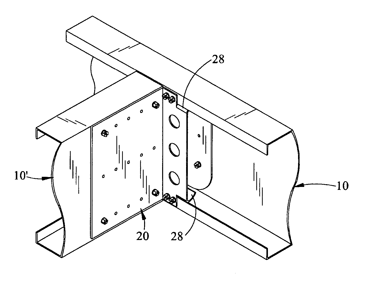
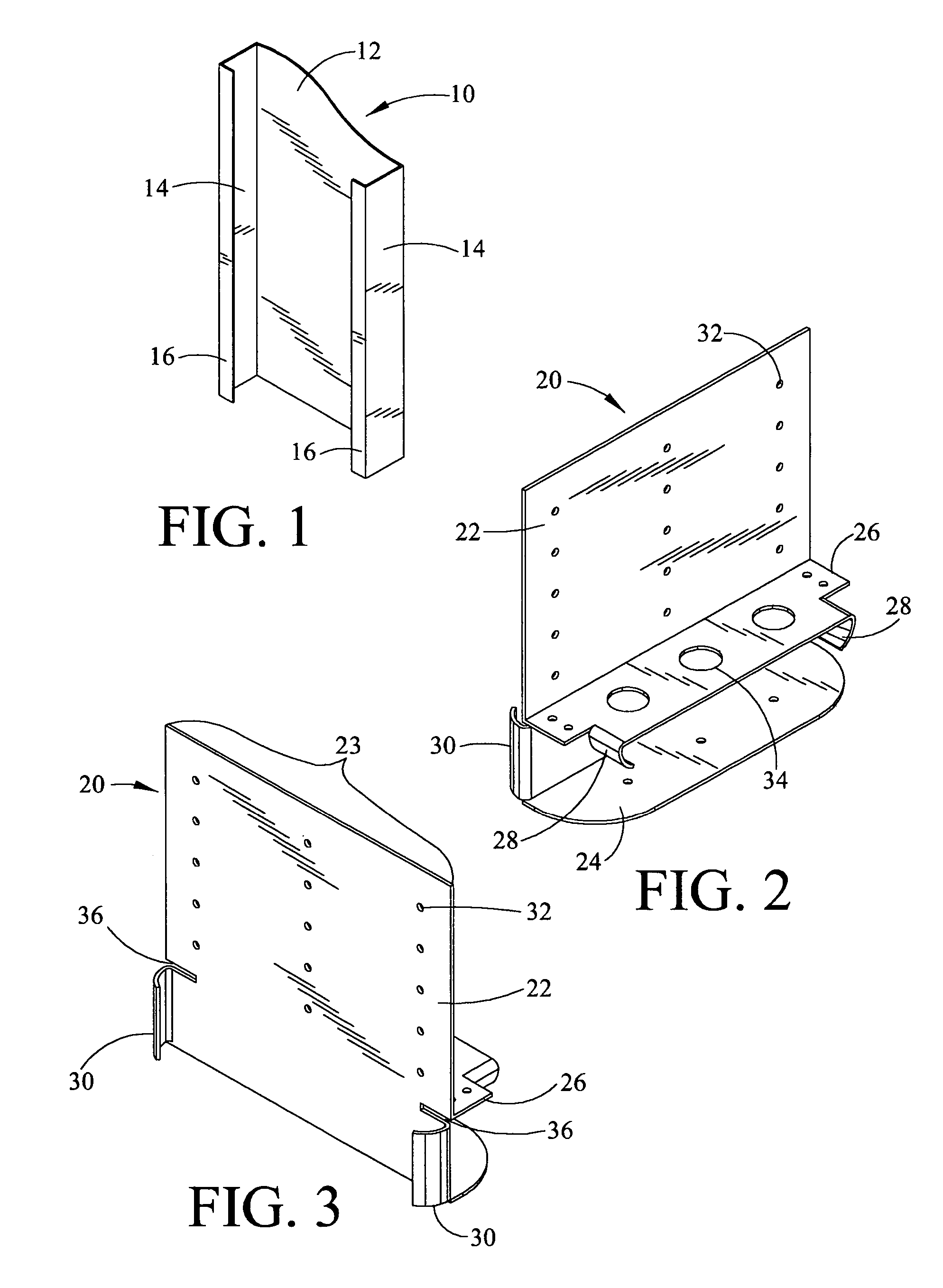
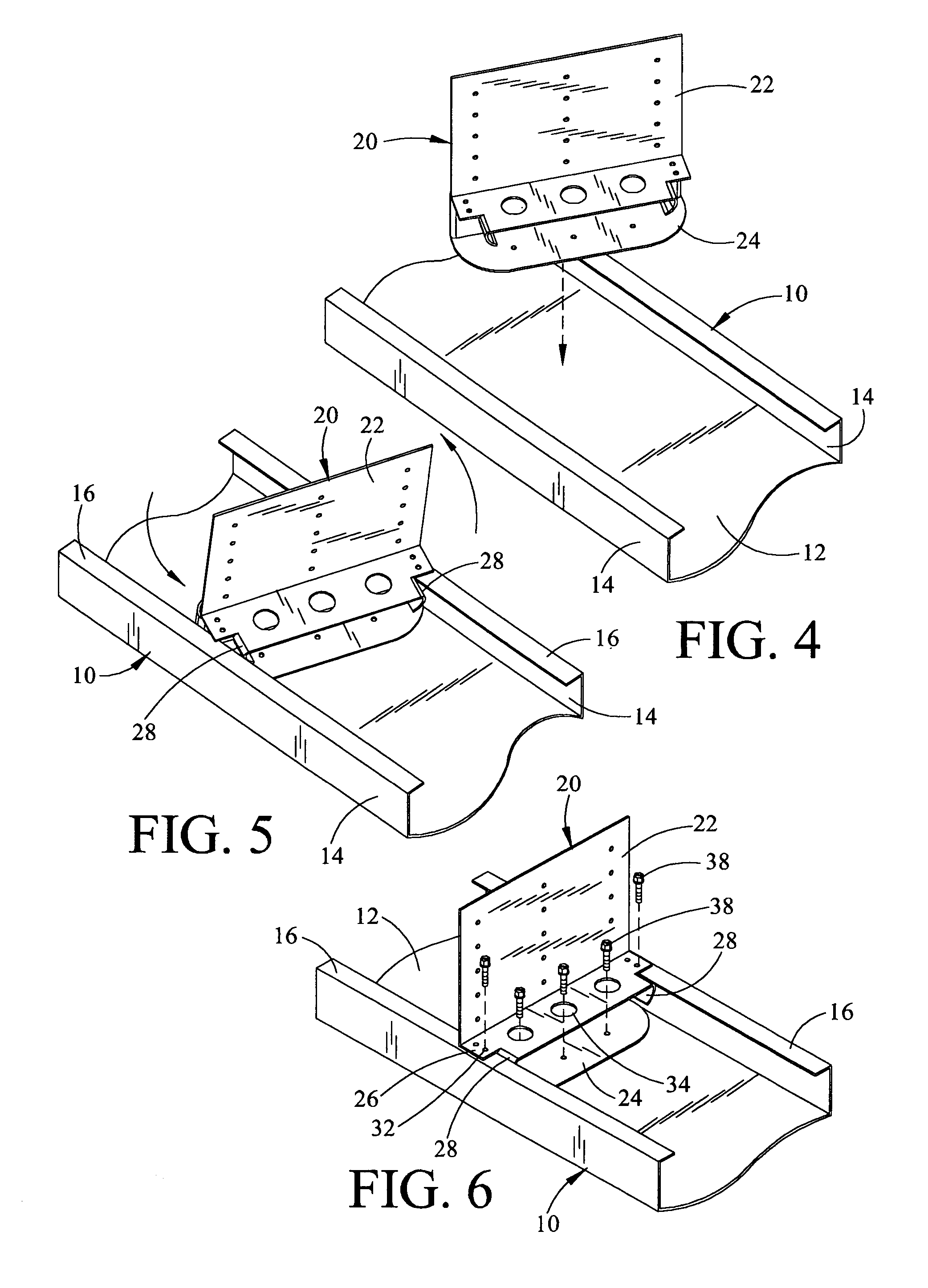
[0145]A conventional U-channel metal framing member or stud 10 is shown in FIG. 1. Framing member 10 comprises a base 12, two sidewalls 14 which extend perpendicular from base 12, and two lips 16 which extend inward from the tops of sidewalls 14 perpendicular thereto and parallel to base 12.

[0146]Member 10 can be of any length, width and depth. Typically member 10 will have a width defined by the width of base 12 that is at least twice its depth defined by the width of sidewalls 14. When substituting for 2″×4″ framing lumber, member 10 will have sidewalls 14 of approximately 2 inches in width and base 12 of approximately 4 inches in width. Lips 16 in this case will extend approximately ⅛ to ½ inch inward from sidewalls 14, although other depths are also possible.

[0147]Member 10 is rolled from steel or aluminum, but could be made of any metal, including stainless steel. The weight and strength of member 10 will be determined by its gauge, which will vary depe...


PUM


Abstract

A novel system for constructing smooth-faced metal framing and novel connectors therefore. The system and connectors of the present invention utilize known metal framing or wall studs that demonstrate a U-channel configuration having a base, sidewalls and marginal lips that extend inward from the sidewalls. A variety structurally related connectors, comprising at least a connector body, base flange, and two lip receiving grooves, are described. These connectors are capable of interconnecting metal framing performing all framing functions including, without limitation, floor and ceiling joists, top and bottom plates, roof rafters, roof rims, window sills, trusses, headers and wall studs. The connectors lock into place within the stud and are secured from the inside using fasteners applied into the non-surface aspects of the stud. The stud connectors demonstrate three dimensional rigidity and a box-like fit within the metal framing studs to form joints that are strong, durable and precise. The framing system using the stud connectors of the present invention leaves the outside surfaces of the framing members and studs smooth and continuous, without protruding fastener heads or interruptions of any sort. The resulting smooth outside surfaces can be covered much more easily and inexpensively than the uneven and generally awkward outside surfaces presently encountered in metal framed structures. The manner in which the connectors lock within the studs promote their safe and efficient installation. The system and connectors of the present invention enables an entire structure to be framed using one type and size of metal framing studs cut to appropriate lengths on site.

Description

CROSS-REFERENCE TO RELATED PATENT APPLICATIONS[0001]This is a (first) division of U.S. Non-provisional application Ser. No. 10 / 046,127, filed Jan. 9, 2002 now U.S. Pat. No. 6,609,344, and granted on Aug. 26, 2003, which application is based in substantial part upon and claims the benefit of U.S. Provisional Application No. 60 / 334,283 filed Nov. 21, 2001.STATEMENT REGARDING FEDERALLY SPONSORED RESEARCH OR DEVELOPMENT[0002]The subject invention is not the result of or in any way related to federally sponsored research or development.BACKGROUND OF INVENTION[0003]1. Field of Invention[0004]The present invention relates to materials and methods for metal framing. In particular, this invention describes an improved system of metal framing that employs specially configured connectors and tracks that leave the faces of the resulting framed structure smooth and easy to cover.[0005]This first divisional application claims a species of structurally related connectors having a connector body, b...

Claims


Application Information

Patent Timeline
Patent Type & Authority Patents(United States)
IPC IPC(8): E04B1/38E04B1/24E04B2/74E04B2/76E04B5/14E04C3/07E04C3/11
CPCE04B1/2403E04B2/767E04B5/14E04C3/07E04C3/11E04B2001/2415E04B2001/2448E04B2001/2457E04B2001/2463E04B2001/2472E04B2001/249E04B2002/7485
Inventor SALDANA, ELUTERIO
Owner SALDANA ELUTERIO
Why Eureka
Try Eureka