Fuel control system and method for gas engines

a technology of fuel control system and gas engine, which is applied in the direction of position/direction control, gaseous engine fuel, special data processing applications, etc., can solve the problems of not being convenient, convenient or economical to install, operate or use, and large amounts of external support equipment and electrical interconnections, so as to reduce or minimize the undesired pollutants in the exhaust, improve the performance of the engine, and reduce the effect of exhaust emissions

Inactive Publication Date: 2009-04-02
CONTINENTAL CONTROLS CORP
View PDF45 Cites 56 Cited by
  • Summary
  • Abstract
  • Description
  • Claims
  • Application Information

AI Technical Summary

Benefits of technology

[0010]This fuel control system is designed specifically for small natural gas engines but may be scaled to work with larger engines. These engines are typically used for power generation, combined cycle (heat and power) applications, gas compression, pump drives, off-road and highway vehicles, and many other stationary mechanical drive applications. The unitary fuel control system may provide a cost effective solution to control the fuel of natural gas engines and may be adjusted to operate in either a rich-burn or a lean-burn mode. Rich-burn or stoichiometric operation uses only the chemically correct amount of air required to burn all the fuel entering the engine, while lean burn operation requires additional air which is not used in the combustion process. The system can maintain a constant or close to constant air / fuel mixture with fast recovery from load or speed transients. When the fuel control system is used on an engine equipped with an appropriate catalytic converter, it can help in complying with strict NOx and CO emissions requirements.
[0029]The fuel control system combines control functions that formerly have been omitted or were not possible in fuel systems consisting of distributed or separate components. The combination makes it possible to share data between sub-systems which enhances the overall control of the engine. In one embodiment, all the control functions are combined into a single unit which has no range limitations and eliminates or reduces the problems of the previous systems. This system can be calibrated on a test bench. When installed on an engine it requires no further adjustment. This fuel system has an additional advantage of being able to run at any air fuel ratio between stoichimetric (rich burn) and very lean.

Problems solved by technology

They have required substantial amounts of external support equipment and electrical interconnections.
They have suffered from slow response and generally have not been particularly easy, convenient or economical to install, operate or use.
Secondly, the increased mass air flow carries the heat away and the combustion takes place at a cooler temperature.
Interaction can occur between the speed governor and the air / fuel system in lean-burn systems, causing the engine speed to be unstable.
However, when running very lean to comply with the emissions requirements, the engine may not have good on-load transient capability.
In other words, if the engine load increases suddenly, it may slow down or even stop running.
This is not possible with the currently available control systems.

Method used


Image

  • Fuel control system and method for gas engines
  • Fuel control system and method for gas engines
  • Fuel control system and method for gas engines

Examples


Embodiment Construction

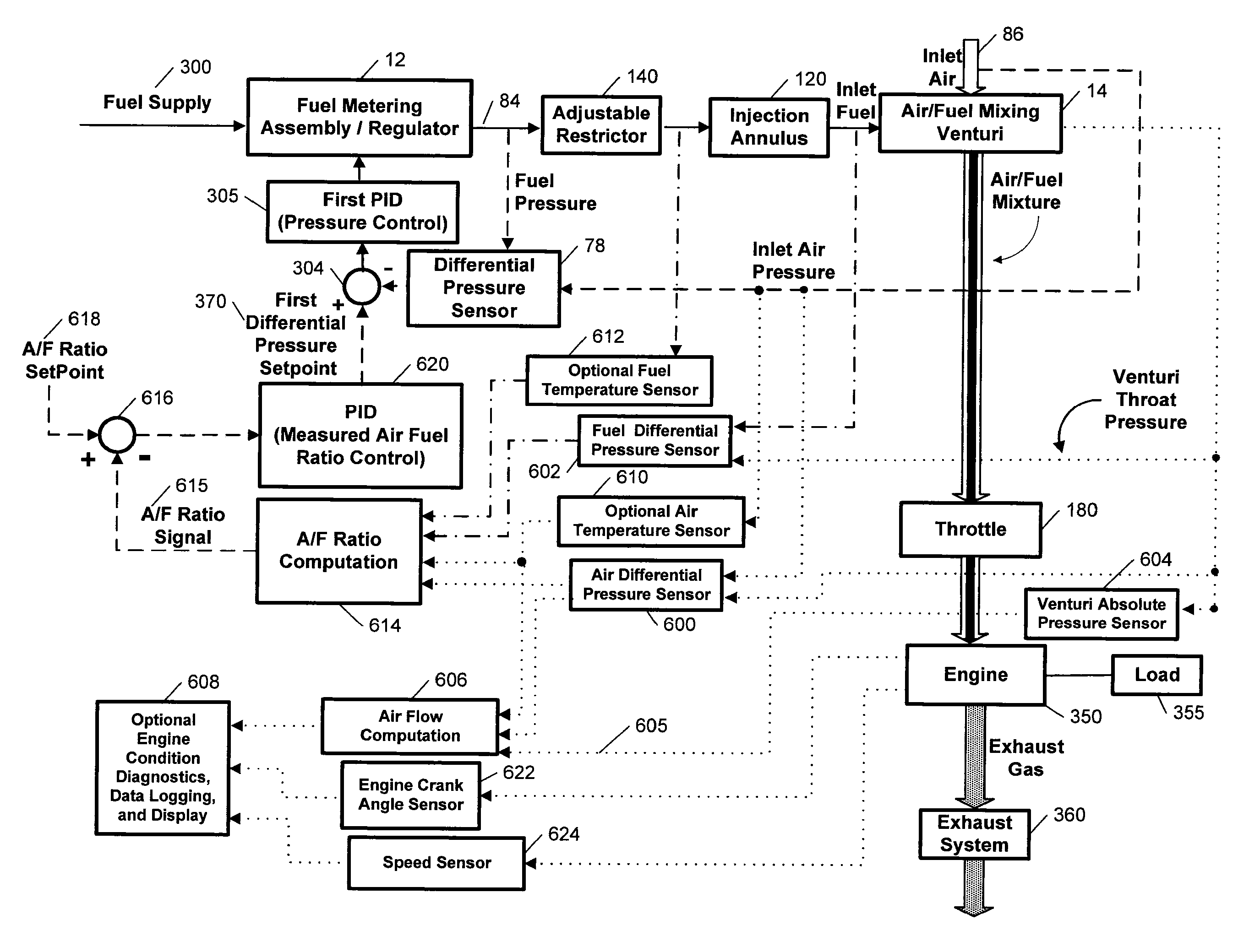
[0065]Certain embodiments as disclosed herein provide for a fuel control or gaseous carburetor system which provides control of the fuel-air ratio in an engine. In some embodiments, the system may also include an integral throttle body and a governor which controls the butterfly or throttle valve, and which is operated by the same controller which controls the fuel-air ratio.

[0066]After reading this description it will become apparent to one skilled in the art how to implement the invention in various alternative embodiments and alternative applications. However, although various embodiments of the present invention will be described herein, it is understood that these embodiments are presented by way of example only, and not limitation. As such, this detailed description of various alternative embodiments should not be construed to limit the scope or breadth of the present invention as set forth in the appended claims.

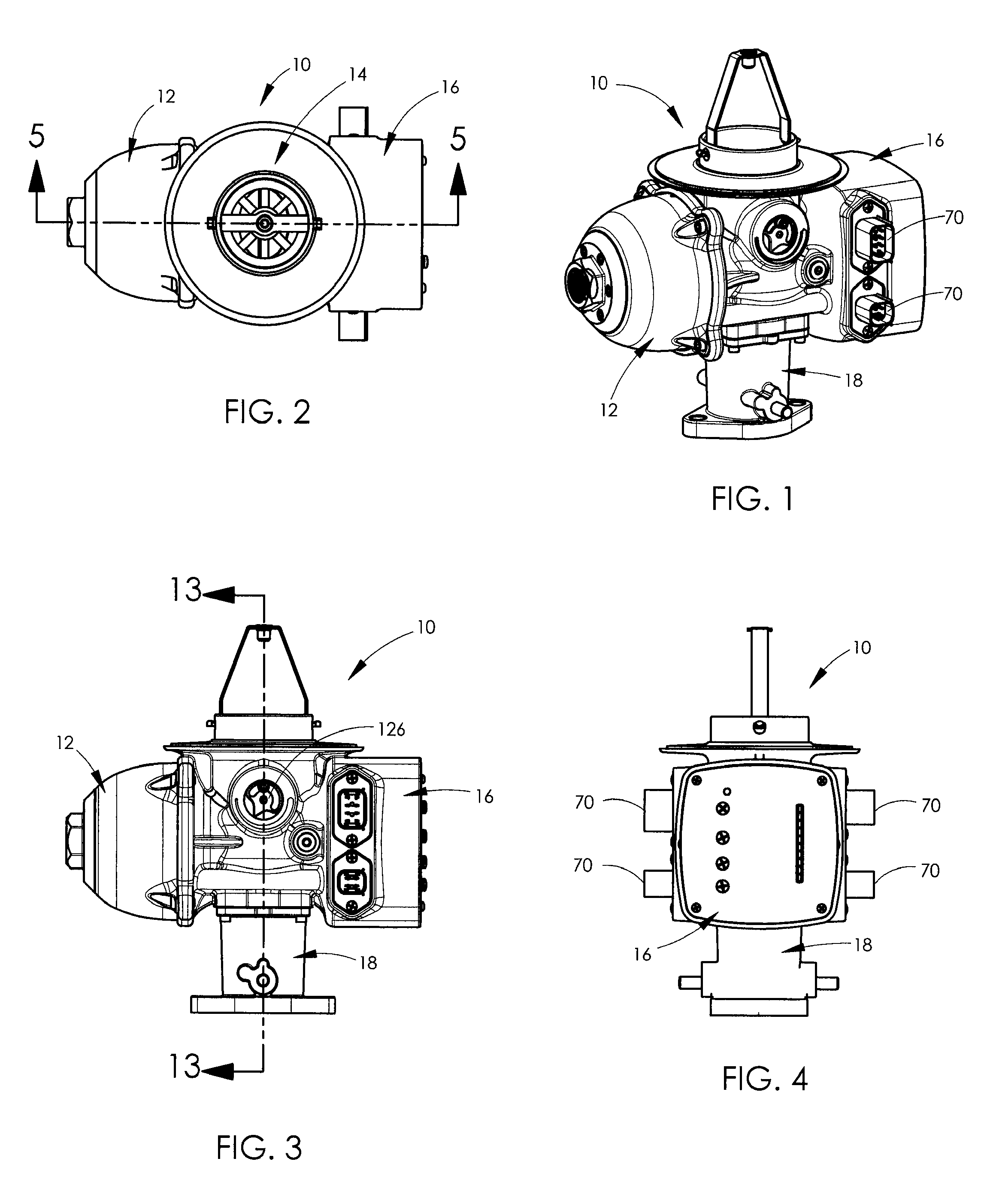
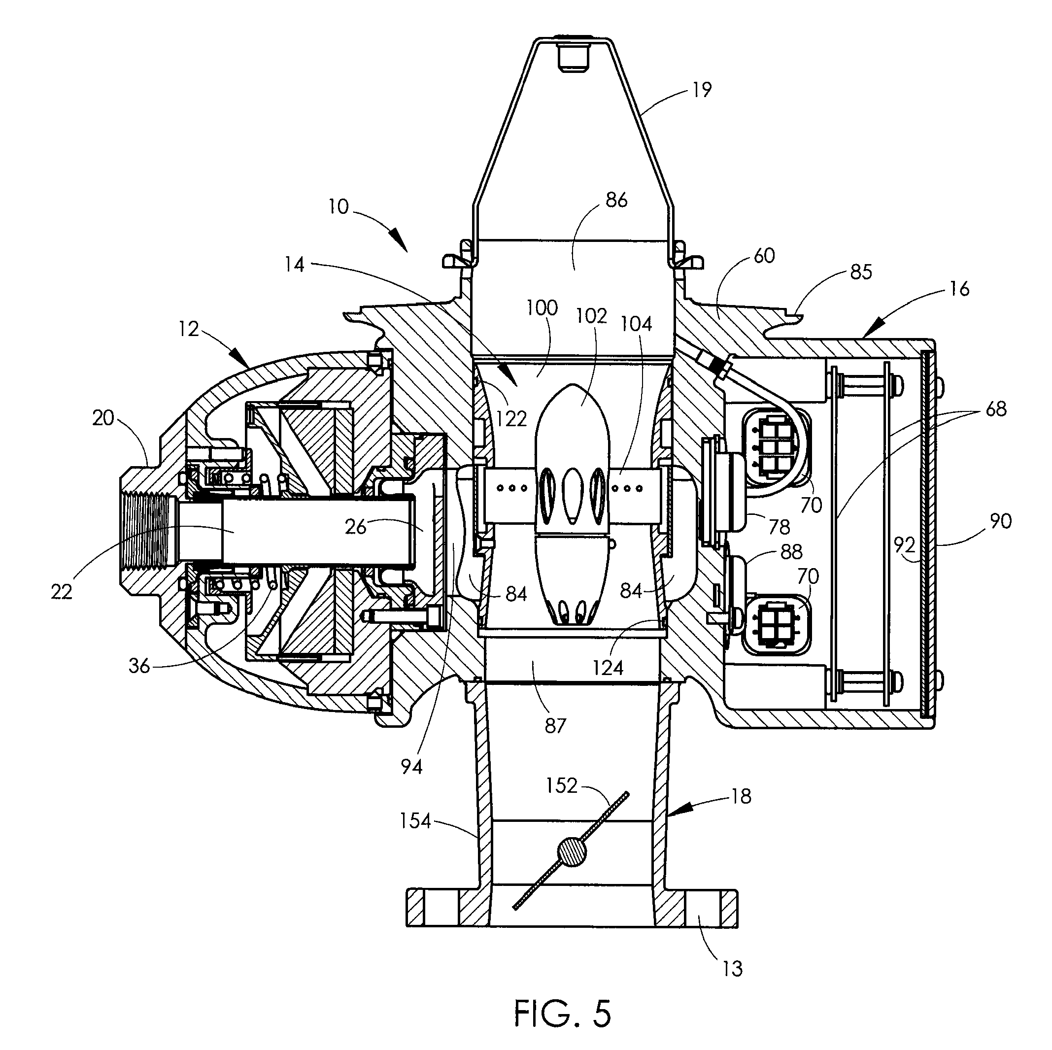
[0067]FIGS. 1 to 19 illustrate one embodiment of a gaseous carbu...


PUM

PropertyMeasurementUnit
pressureaaaaaaaaaa
differential pressureaaaaaaaaaa
differential pressure sensoraaaaaaaaaa

Abstract

A gaseous carburetor or fuel control system includes a fuel metering assembly, a venturi mixer assembly, a throttle assembly, and an electronic control unit. The control unit controls the fuel metering assembly in a closed loop manner based on detected gas and air pressure to an air / fuel mixing venturi. An electronic governor which controls the throttle valve may also be controlled by the same control unit which controls the fuel metering assembly, using a separate control loop.

Description

RELATED APPLICATION [0001]The present application claims the benefit of co-pending U.S. provisional patent application No. 60 / 975,742 filed Sep. 27, 2007, which is incorporated herein by reference in its entirety.BACKGROUND [0002]1. Field of the Invention[0003]This invention relates generally to devices and systems for mixing natural gas or any gaseous fuel with air in the correct proportions for combustion in a gas engine, and is particularly concerned with a fuel control system and method for controlling a natural gas engine for the purpose of reducing exhaust emissions and improving engine performance.[0004]2. Related Art[0005]The main concern that engineers had when designing the older engines and their fuel systems was engine performance and durability without any regard for exhaust emissions. Over the years numerous systems for controlling emissions have evolved utilizing a catalytic converter, an exhaust gas sensor, and a fuel modulating system to control the mixture for redu...

Claims


Application Information

Patent Timeline
Patent Type & Authority Applications(United States)
IPC IPC(8): F02D41/00F02M19/08F02M9/02
CPCF02D31/002F02D35/0076F02D41/0027F02D41/1401F02D41/1454F02D41/146F02D41/187F02D2041/1409F02D2041/1419F02D2041/1422F02D2200/0404F02D2200/0406F02M19/08F02M21/047F02M21/0239F02D19/023F02D19/027Y02T10/30
Inventor FISHER, C. ROSSYATES, KRISTIAN W.FISHER, DAVID G.MANSFIELD, GEORGE A.
Owner CONTINENTAL CONTROLS CORP
Why Eureka
Try Eureka