

Connector device and locking structure
- Summary
- Abstract
- Description
- Claims
- Application Information
AI Technical Summary
Benefits of technology
Problems solved by technology
Method used
Image

Examples
first embodiment
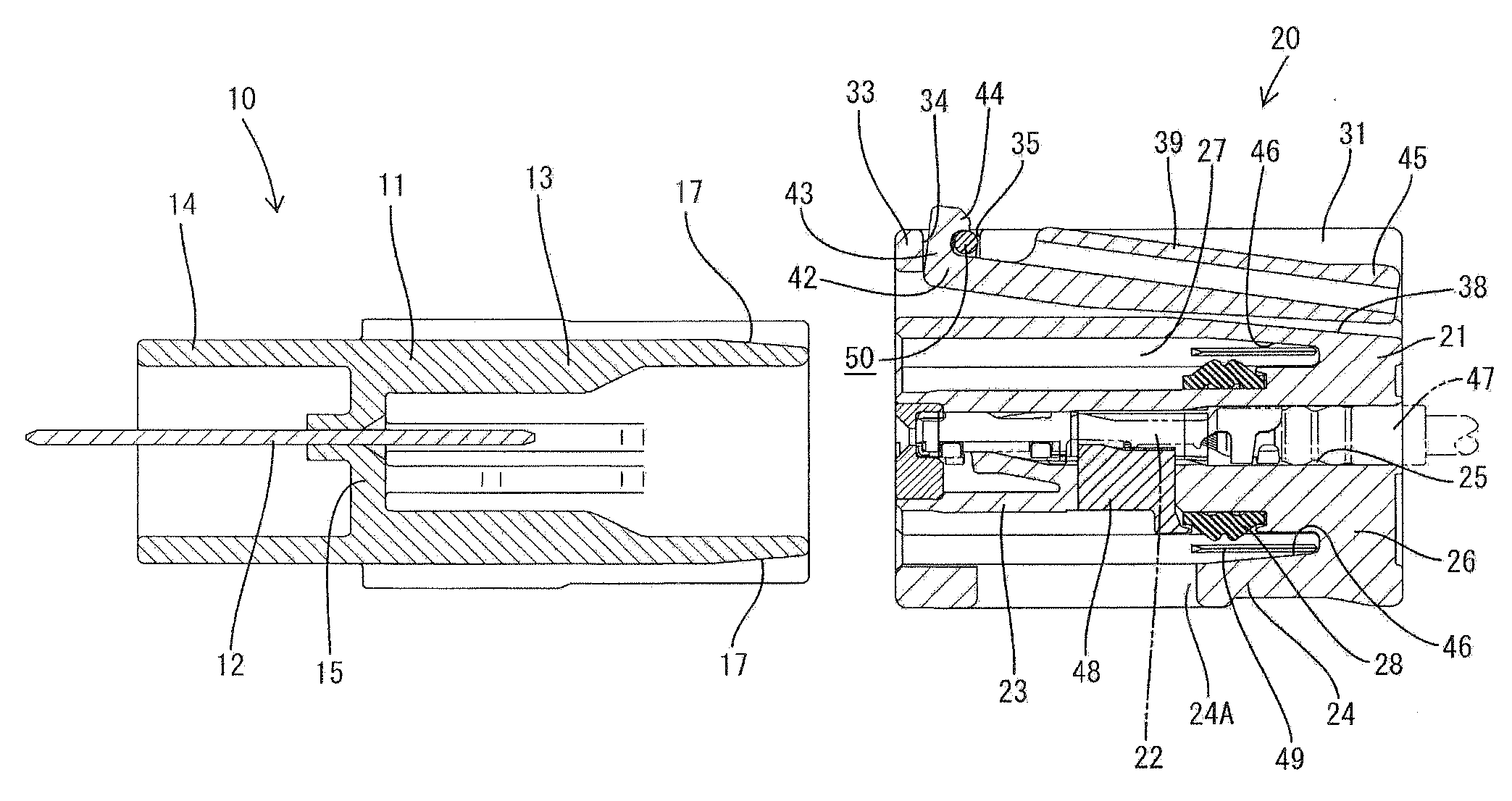
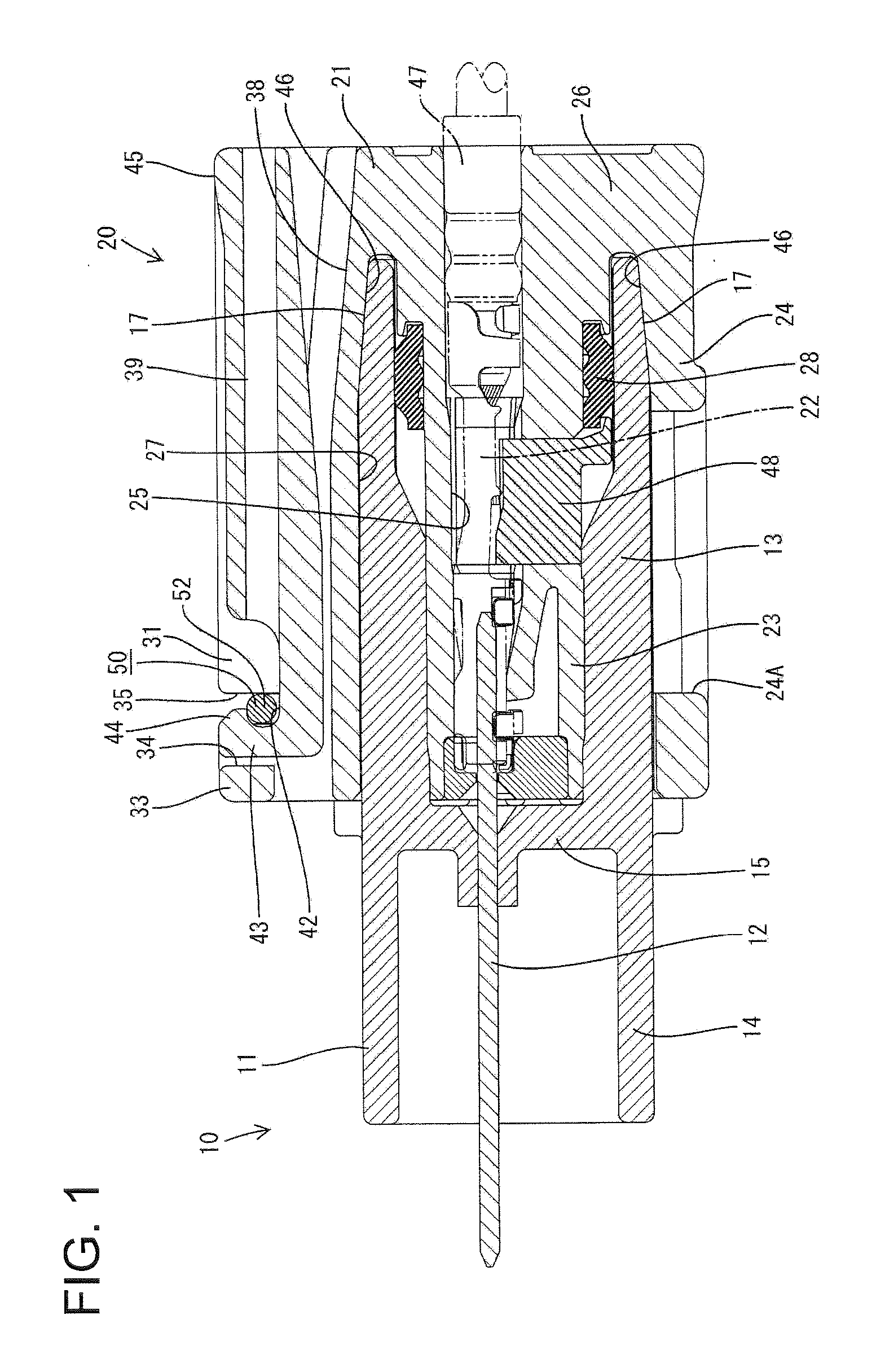
[0072]A connector in accordance with the invention is illustrated in FIGS. 1 to 7 and includes a male connector 10 and a female connector 20 that are connectable with each other. Ends of the two connectors 10, 20 that are connected to one another are referred to herein as the front ends and reference is made to FIG. 1 concerning upper and lower sides.
[0073]The male connector 10 includes a male housing 11 and male terminals 12 are held in the male housing 11. The male housing 11 is made e.g. of synthetic resin and includes front and rear receptacles 13 and 14, each of which is a wide substantially rectangular tube. The front receptacle 13 has an open front end and the rear receptacle 14 has an open rear end. The thickness of the front portion of the front receptacle 13 in inward and outward directions is less than the thickness of the rear portion of the front receptacle 13. Engaging projections 16 project laterally out from the opposite left and right surfaces of the male housing 11...
second embodiment
[0114]the invention is illustrated in FIGS. 8 to 15 and relates to a locking structure for locking female and male connectors F and M together. Ends of the two connectors to be connected are referred to as front ends and reference is made to FIG. 8 concerning upper and lower sides.
[0115]The male connector M includes a male housing 150 and male terminals 151 are held in the male housing 150. The male housing 150 is made e.g. of synthetic resin and includes wide tubular front and rear receptacles 152 and 153. The front receptacle 152 has an open front end and the rear receptacle 153 has an open rear end. Male terminals 151 are held while penetrating a back wall 154 between the front and rear receptacles 152 and 153 of the male housing 150. Front and rear parts of the male terminals 151 project forward and backward in the front and rear receptacles 152 and 153.
[0116]Engaging projections 155 project laterally out from the left and right surfaces of the male housing 150. The engaging pro...
PUM
 Abstract
Description
Claims
Application Information