Discharging control apparatus of switching device for inverter

a technology of inverter switching device and control apparatus, which is applied in the field of inverter, can solve the problems of damage to the switching device, high level of spike voltage, and large current capacity of the switching device to be outputted to a load, so as to prevent an extension of the turn-off time of the switching device and reduce the spike voltage

Active Publication Date: 2009-05-07
LS IND SYETEMS CO LTD
View PDF13 Cites 4 Cited by
  • Summary
  • Abstract
  • Description
  • Claims
  • Application Information

AI Technical Summary

Benefits of technology

[0028]Therefore, an object of the present invention is to provide a discharging control apparatus of a switching device for an inverter capable of reducing a spike voltage, which is generated when the switching device is turned off in the state that a normal current flows in the switching device, and also of preventing an extension of a turn-off time of the switching device.
[0029]Another object of the present invention, there is provided a discharging control apparatus of a switching device for an inverter capable of preventing a damage of the switching device and reducing a spike voltage, by fast discharging a gate voltage when the switching device is turned off in the state that an over-current flows in the switching device.

Problems solved by technology

In the inverter, particularly, in a large capacity inverter, the capacity of current which is switched by the switching device to be outputted to a load is very large.
Thus, even during the normal operation of the inverter, a high level of spike voltage may be generated when the switching device is turned off.
Such spike voltage may damage the switching device.
However, the increase in the resistance value of the resistor R2 causes a turn-off time of the switching device IGBT to be extended, resulting in an increase in the loss of the switching device IGBT
In addition, in the gate driving unit of the switching device for the inverter according to the related art, when turning the switching device off under the state that an over-current flows in the switching device, the spike voltage is much increased, thereby damaging the switching device (e.g., burning it out).

Method used


Image

  • Discharging control apparatus of switching device for inverter
  • Discharging control apparatus of switching device for inverter
  • Discharging control apparatus of switching device for inverter

Examples


Embodiment Construction

[0040]Description will now be given in detail of configuration and operational effects of the present invention, with reference to the accompanying drawings.

[0041]The embodiment and accompanying drawings described herein are merely exemplary, and other various embodiments may be proposed within the scope of the present invention. Also, it should be understood such embodiment and accompanying drawings are not intended to limit the range of the present invention.

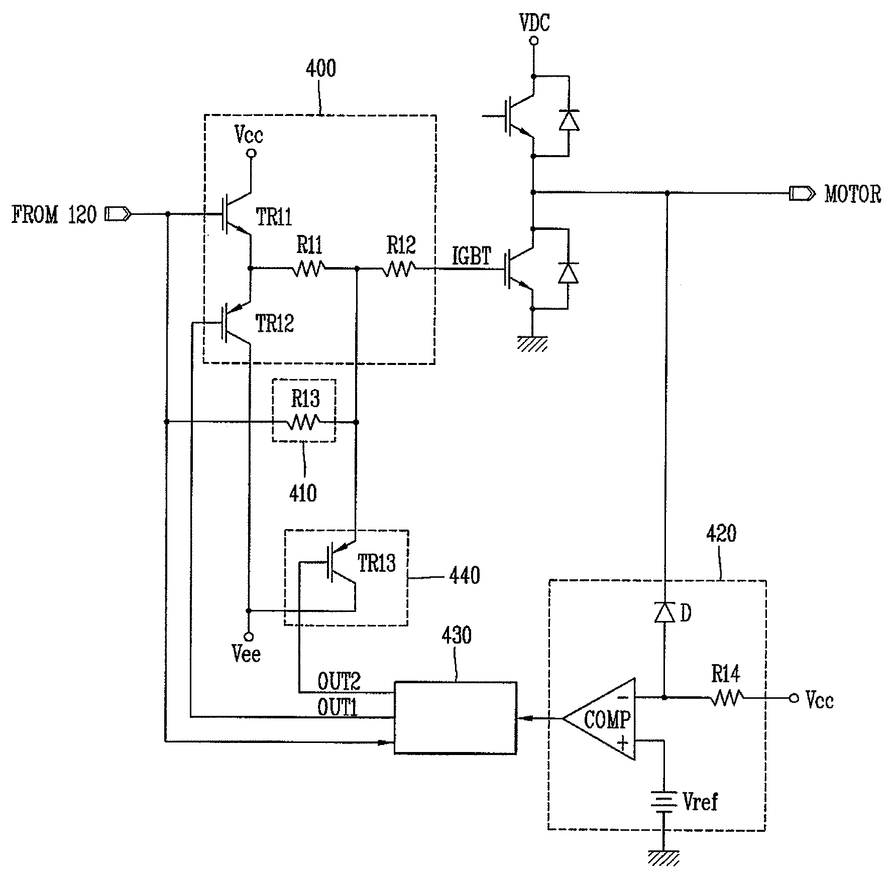
[0042]Hereinafter, description will be given of an exemplary configuration of a driving unit of a switching device, including a discharging control apparatus in a switching device for an inverter in accordance with a preferred embodiment of the present invention, with reference to FIG. 4.

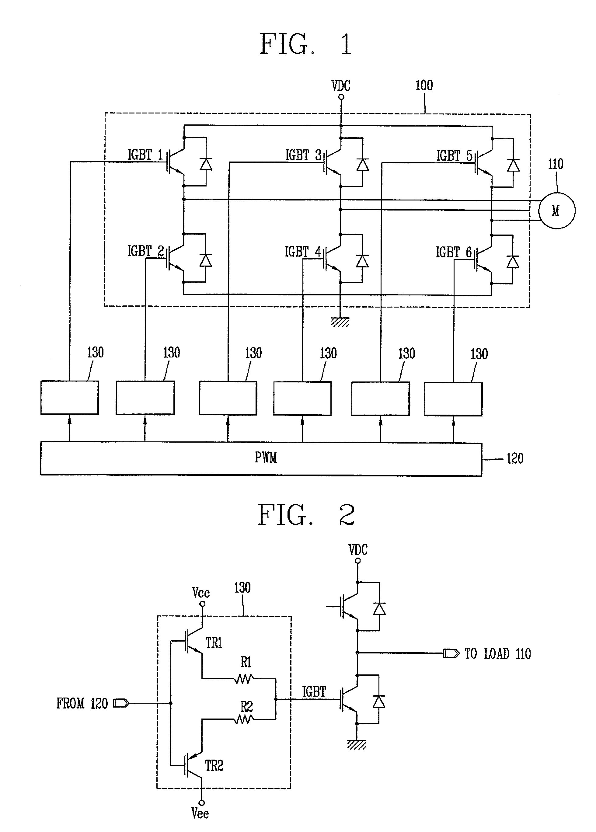
[0043]As shown in FIG. 4, a discharging control apparatus of a switching device for an inverter in accordance with a preferred embodiment of the present invention includes a first fast discharge circuit section (i.e., R11, R12 and TR12) for pr...


PUM


Abstract

Disclosed is a discharging control apparatus of a switching device for an inverter capable of reducing a spike voltage when the switching device is turned off and reducing a turn-off time of the switching device, the apparatus comprising, a fast discharge circuit section configured to provide a discharging path through which a gate voltage of the switching device is fast discharged at a first discharging speed, an idle discharge circuit section configured to provide a discharging path through which the gate voltage of the switching device is idly discharged at a second discharging speed slower than the first discharging speed, and a spike voltage reduction controller configured to control such that the gate voltage is discharged simultaneously via the fast discharge circuit section and the idle discharge circuit section, when the switching device is turned off in the state that a normal current flows in the switching device, so as to reduce a spike voltage and simultaneously fast turn the switching device off.

Description

RELATED APPLICATION[0001]The present disclosure relates to subject matter contained in Korean Application No. 10-2007-0112729, filed on Nov. 6, 2007, which is herein expressly incorporated by reference in its entirety.BACKGROUND OF THE INVENTION[0002]1. Field of the Invention[0003]The present invention relates to an inverter, and particularly, to a discharging control apparatus of a switching device for an inverter.[0004]2. Background of the Invention[0005]In general, an inverter is widely used to drive alternating current (AC) loads, such as a three-phase alternating current (AC) motor or the like. The inverter serves to convert a commercial AC voltage into a direct current (DC) voltage and to invert the DC voltage into AC voltage again. Wherein the converted DC voltage is switched by a switching device to be then inverted to the AC voltage again, so as to be supplied to a load, such as an AC motor. And the inverter can accurately control the velocity of the three-phase AC motor.[0...

Claims


Application Information

Patent Timeline
Patent Type & Authority Applications(United States)
IPC IPC(8): H02H9/00
CPCH03K17/168H03K17/166H03K17/08H02M1/08
Inventor KIM, JIN-HONG
Owner LS IND SYETEMS CO LTD
Why Eureka
Try Eureka