Work piece carrier for exactly positioning a work piece on a chuck and clamping apparatus with a chuck and a work piece carrier

a work piece and carrier technology, applied in the field of work piece carriers, can solve the problems of time-consuming, inaccuracy, and work piece fixing to the work piece carrier can only be machined on one side, and achieve the effect of accurate definition and well-known, simple and rigid design

Inactive Publication Date: 2009-07-16
EROWA
View PDF11 Cites 4 Cited by
  • Summary
  • Abstract
  • Description
  • Claims
  • Application Information

AI Technical Summary

Benefits of technology

[0010]It is an object of the present invention to provide a work piece carrier having a central aperture of the kind referred to herein above which can be attached to different chuck members quickly, simply, and in different positions, whereby the particular position is accurately defined and well known. Nevertheless, such a work piece holder shall be of simple and rigid design.
[0013]Due to the fact that the work piece carrier is provided with two reference systems that are independent of each other, whereby means for fixing the work piece carrier to the chuck member, extending substantially in the direction of the central longitudinal axis of the work piece carrier and surrounding this central opening, are assigned to each reference system, the fundamental prerequisite is created that the work piece carrier can be attached to a chuck member quickly, simply, safely and in an accurate, well defined position without the use of a centrally located clamping bolt member.
[0014]According to a second aspect, the present invention provides a clamping apparatus with a chuck member and a work piece carrier adapted to be releaseably attached to the chuck member. The chuck member is provided with a reference system for defining the position of a work piece carrier attached to the chuck member as well as with clamping elements for clampingly hold a work piece carrier attached to the chuck member. The work piece carrier comprises a central aperture extending in the direction of its central longitudinal axis and is adapted to receive a work piece. The carrier comprises a first reference system provided with first centering elements and adapted to cooperate with the reference system of the chuck member to align the work piece carrier with regard to the chuck member in a first accurately defined position.

Problems solved by technology

A disadvantage of such a known apparatus is, amongst else, that a work piece fixed to the work piece carrier can be machined only on one side.
It is understood that such a proceeding, on the one hand, is time consuming and, on the other side, brings along inaccuracies as far as the exact position of the work piece is concerned.
Even if the annular rib engaging the assigned annular groove allows for some kind of positioning of the clamping frame with regard to the spindle head, no means are provided for exactly and accurately aligning the clamping frame with regard to the spindle head both in the X-and Y-directions as well as in the Z-direction.
Moreover, the chuck member cannot be released from the spindle and, if required, attached to the spindle of another machine tool.
A further disadvantage may be seen in the fact that a work piece received in the clamping frame is limited in size; if it is too large, particularly too long, the clamping frame cannot be turned over by 180° anymore without removing the work piece.

Method used


Image

  • Work piece carrier for exactly positioning a work piece on a chuck and clamping apparatus with a chuck and a work piece carrier
  • Work piece carrier for exactly positioning a work piece on a chuck and clamping apparatus with a chuck and a work piece carrier
  • Work piece carrier for exactly positioning a work piece on a chuck and clamping apparatus with a chuck and a work piece carrier

Examples


Embodiment Construction

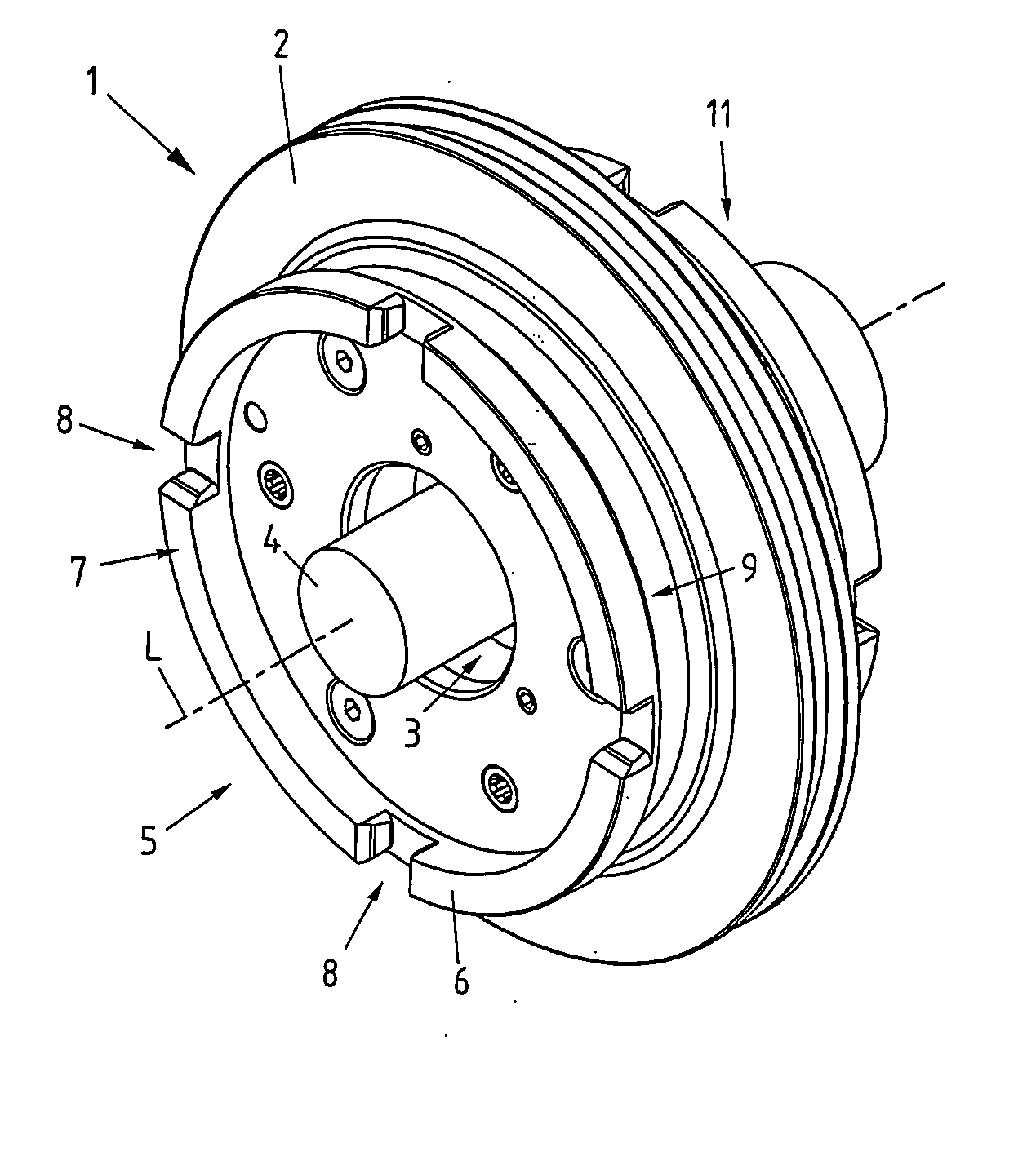
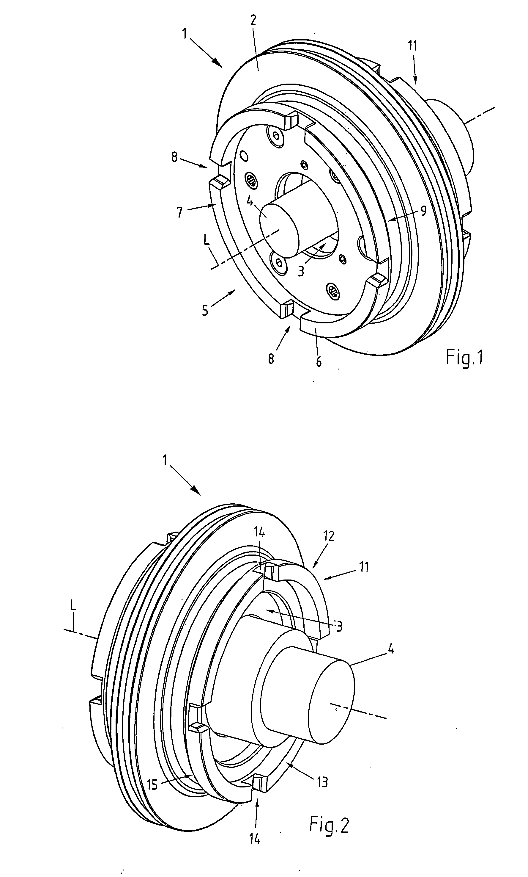
[0023]FIG. 1 shows the work piece carrier 1, together with a work piece 4 clamped therein, in a perspective view from one side. The work piece carrier comprises a circular, disk-like base body member 2 which is provided with a central aperture 3. The diameter of the aperture 3 is not constant, but the aperture 3 has a portion with a first, smaller diameter and a portion with a second, larger diameter. The work piece carrier 1 is provided with two reference systems 5, 11, located opposite to each other on the two sides of the work piece carrier 1. In FIG. 1, the first reference system 5 is fully visible, while only a portion of the second reference system 11 can be seen. The first reference system 5 comprises a protrusion 6 having essentially annular shape, extending parallel to and coaxial with the central longitudinal axis L of the work piece carrier 1. Simultaneously, the central longitudinal axis L of the work piece carrier 1 constitutes the Z-axis of the work piece carrier 1.

[00...


PUM

PropertyMeasurementUnit
angleaaaaaaaaaa
elasticaaaaaaaaaa
forcesaaaaaaaaaa

Abstract

A work piece carrier is provided with two reference systems for accurately positioning it with regard to a chuck member. The work piece carrier comprises a central aperture with the two opposite ends of the aperture surrounded by one of the reference systems. The two reference systems are independent from each other and allow the work piece carrier to be attached to the chuck member in two different positions. Assigned to each reference system is a protrusion surrounding the central aperture and extending substantially in the direction of the central longitudinal axis of the work piece carrier. The particular protrusion is provided with a shoulder serving as a clamping surface, adapted to be engaged by clamping elements provided in the chuck member. Preferably, also the centering elements for defining the position of the work piece carrier with regard to the chuck member are located on the particular protrusion.

Description

BACKGROUND[0001]The present invention refers to a work piece carrier, having a central aperture for receiving the work piece as well as two reference systems, each incorporating positioning elements, to releaseably attach the work piece carrier to a chuck member in two different, well defined positions. The present invention also refers to a clamping apparatus, comprising a chuck member and a work piece carrier that can be attached thereto in two different positions.[0002]Well known in the prior art are clamping apparatuses to attach a work piece to a chuck member of a machine tool with high precision by means of a work piece carrier. Thereby, the work piece carrier shall not only be attached to the chuck member with high absolute precision, but particularly also a high repetitional accuracy. In order to enable the work piece carrier to be attached to a chuck member in an exactly defined position, the work piece carrier usually is provided with a reference system that is matched to ...

Claims


Application Information

Patent Timeline
Patent Type & Authority Applications(United States)
IPC IPC(8): B23Q3/00B23B5/34
CPCB23B31/1071B23B31/201B23B31/34B23B2270/12Y10T279/3406B23Q1/0063Y10T279/1033Y10T279/17008B23B2270/14
Inventor SANDMEIER, BRUNO
Owner EROWA
Why Eureka
Try Eureka