
Receiver with frequency offset compensation for M-state phase modulation

a phase modulation and frequency offset technology, applied in the field of telecommunication systems, can solve the problems of affecting the overall performance of the receiver, affecting the quality of the receiver, and affecting the overall performance, so as to achieve the effect of improving the granulation of samples, and fine tuning of frequency offs

Inactive Publication Date: 2012-04-10
STMICROELECTRONICS BELGIUM
View PDF20 Cites 0 Cited by
  • Summary
  • Abstract
  • Description
  • Claims
  • Application Information

AI Technical Summary

Benefits of technology

[0012]An object of the present invention is to provide an improvement of frequency offset compensation as used in wireless receivers. For example the compensation can be used in wireless receivers using M-state phase modulation, especially M-state differential phase modulation such as in a Bluetooth radio demodulator for EDR operation. An advantage of the present invention is that direct frequency offset compensation on the received signals can be avoided.
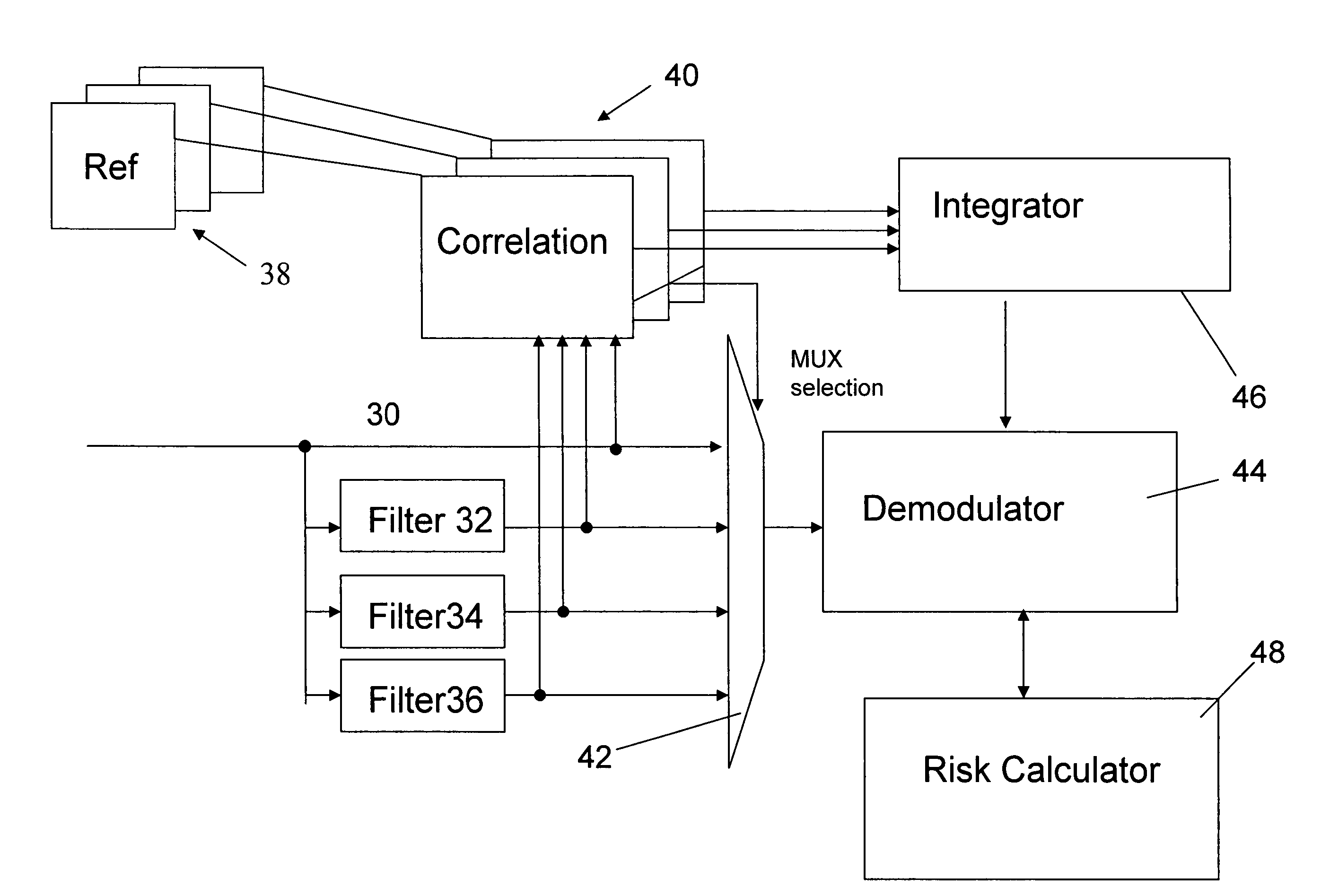
[0013]The present invention provides a receive path in a receiver comprising: means for deriving at least a first stream of first digitized samples from a received analog signal at a first sampling rate, and means for identifying a first frequency offset based on a plurality of parallel correlations using complex reference signals which differ from each other by phase offsets. By selecting the phase offsets to be small, a fine tuning of the frequency offset can be obtained.
[0014]The present invention also provides a receive path in a receiver comprising: means for deriving at least a first stream of first digitized samples from a received analog signal at a first sampling rate, and means for identifying a second frequency offset based on tracking a demodulation accuracy for each symbol which is demodulated from the first stream of digitized samples. By selecting an accurate method of obtaining the demodulation accuracy a fine tuning of the frequency offset can be obtained. The demodulation accuracy can be an error value referred to an optimum demodulated symbol point. This can be obtained easily from the demodulated signals. The demodulation accuracy is preferably a phase error as this can be used directly to rotate decision areas, i.e. phase rotate the decision boundaries of the decision areas used to identify symbols. Alternative modulation accuracies can be used, e.g. the demodulation accuracy can be a value related to EVM or DEVM for each demodulated symbol.
[0015]The complex reference signals preferably differ from each other by phase offsets which lie within one decision area for the demodulated symbols. This makes a fine tuning of the frequency offset to values which results in only a fractional change in the position of demodulated symbols in the decision areas.
[0016]The means for identifying a first frequency offset obtains the first frequency offset by summing a correlation value for each correlation over a number of signal samples. The correlation value can be a value related to an energy when received samples are combined with the reference signals, the reference signals being derived from a known sequence in the received analog signal. The basic technique is well known and is easily implemented.
[0017]Optionally, at least one interpolating filter is provided in parallel with the first stream of first digitized samples for generating at least a second stream of digitized samples at the first sampling rate but offset with respect to the first stream by a fraction of a sample time period. This increases the granulation of the samples and therefore improves correlation.

Problems solved by technology

One of the distortion problems that needs to be compensated in a wireless receiver such as a Bluetooth receiver using EDR is carrier frequency offset.
Although this type of frequency offset works well when the number of constellation points is low, the introduction of more complex modulation schemes means that frequency offset has a more serious effect, e.g. on bit errors for long packets in 3 Mbps EDR (3-DH5 packets).
Determining an optimum predetermined correlation threshold suitable for all reception conditions can be difficult.
Compensating directly on the signal can bring degradation to the overall performance and an increase in complexity.
The received signal must be rotated and de-rotated, such multiplications being very costly as far as implementation cost goes.
Degradation can occur as such rotations on the demodulated signals always bring along approximations which introduce errors.

Method used


Image

  • Receiver with frequency offset compensation for M-state phase modulation
  • Receiver with frequency offset compensation for M-state phase modulation
  • Receiver with frequency offset compensation for M-state phase modulation

Examples


Embodiment Construction

[0037]The present invention will be described with reference to certain drawings and to certain embodiments but this description is by way of example only. The terms “first”, “second” etc. do not necessarily refer to a specific sequence of events in time or space unless there is specific reference to such a sequence. The present application relates to telecommunication devices especially wireless communication devices using M-ary modulation, e.g. M-state phase modulation with M equal to 2 or greater than 2, especially M-state differential phase modulation with M equal to 2 or greater than 2, i.e. the symbols are demodulated as phase differences between digitized signals rather than from absolute phase values. Specific examples will be described with reference to 8-DPSK, but the present invention can be applied to any modulation scheme using a plurality of constellation points, e.g. 2 or greater than 2, especially when differential phase modulation is used.

[0038]The present invention...


PUM


Abstract

Method and apparatus for a wireless receiver are described which derive at least a first stream of first digitized samples from a received analog signal at a first sampling rate and identify a first frequency offset based on a plurality of parallel correlations using complex reference signals which differ from each other by phase offsets. A second frequency offset is identified based on tracking a demodulation accuracy for each symbol which is demodulated from the first stream of digitized samples. These frequency offsets can be used to rotate decision areas in the demodulator. The methods and apparatus may be used in a Bluetooth receiver.

Description

BACKGROUND OF THE INVENTION[0001]1. Field of the Invention[0002]The present invention relates to telecommunication systems especially wireless systems, wireless transmitters and wireless receivers, especially those using the Bluetooth standard. The present invention also relates to semiconductor integrated circuits that implement a wireless receiver and / or a wireless transmitter especially those using the Bluetooth standard, as well as software for implementing the transmitter and / or receiver.[0003]2. Technical Background[0004]The Bluetooth wireless interface, introduced by the Bluetooth Special Interest Group (Ericsson, Nokia, IBM, Toshiba and Intel) in 1998, is designed to be a low-cost, low-power and short-range cable replacement.[0005]Version 2.0+EDR of the Bluetooth standards introduces an Enhanced Data Rate (EDR) operation. The EDR standard is an improvement over the Basic Rate standard. New modulation schemes based on M-state phase modulation (M greater than 2) are proposed: ...

Claims


Application Information

Patent Timeline
Patent Type & Authority Patents(United States)
IPC IPC(8): H04L27/06
CPCH04L27/22H04L2027/0065H04L2027/0095
Inventor CAPRETTA, PIETROTERRYN, STEVENSCHMIT, JEAN-JACQUES
Owner STMICROELECTRONICS BELGIUM
Learn More