Adjustable Width Trocar

a width and trocar technology, applied in the field of adjustable width trocar, can solve the problems of eye trauma at the incision site, additional time for making the widening incision, and additional expense of purchasing a second kni

Inactive Publication Date: 2009-07-16
ALCON RES LTD
View PDF12 Cites 4 Cited by
  • Summary
  • Abstract
  • Description
  • Claims
  • Application Information

AI Technical Summary

Benefits of technology

[0006]The present invention improves upon prior art by providing a trocar having a blade split into two portions, a fixed portion and a movable portion. The movable portion is attached to the fixed portion at a pivot point that allows the movable blade portion to ext

Problems solved by technology

This repeated removal and insertion can cause trauma to the eye at the incision site.
This requires addit

Method used


Image

  • Adjustable Width Trocar
  • Adjustable Width Trocar
  • Adjustable Width Trocar

Examples


Embodiment Construction

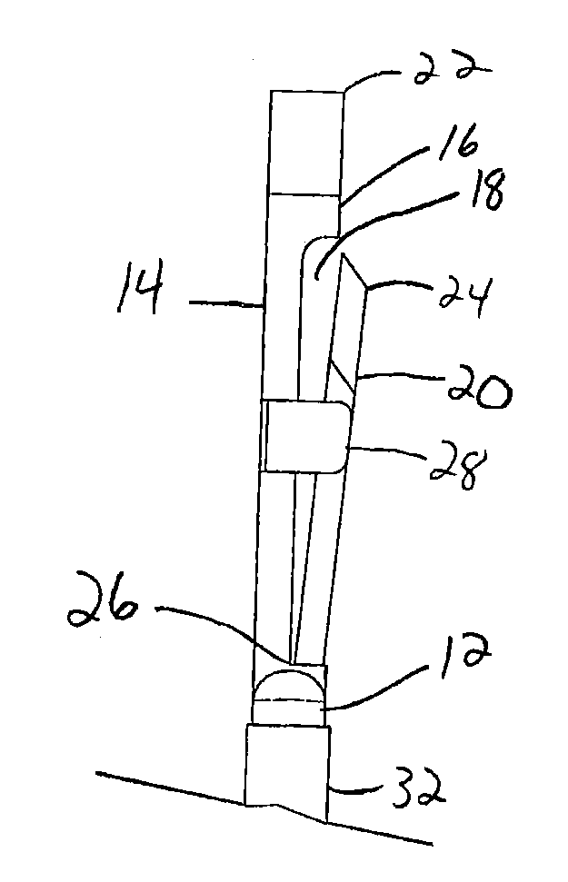
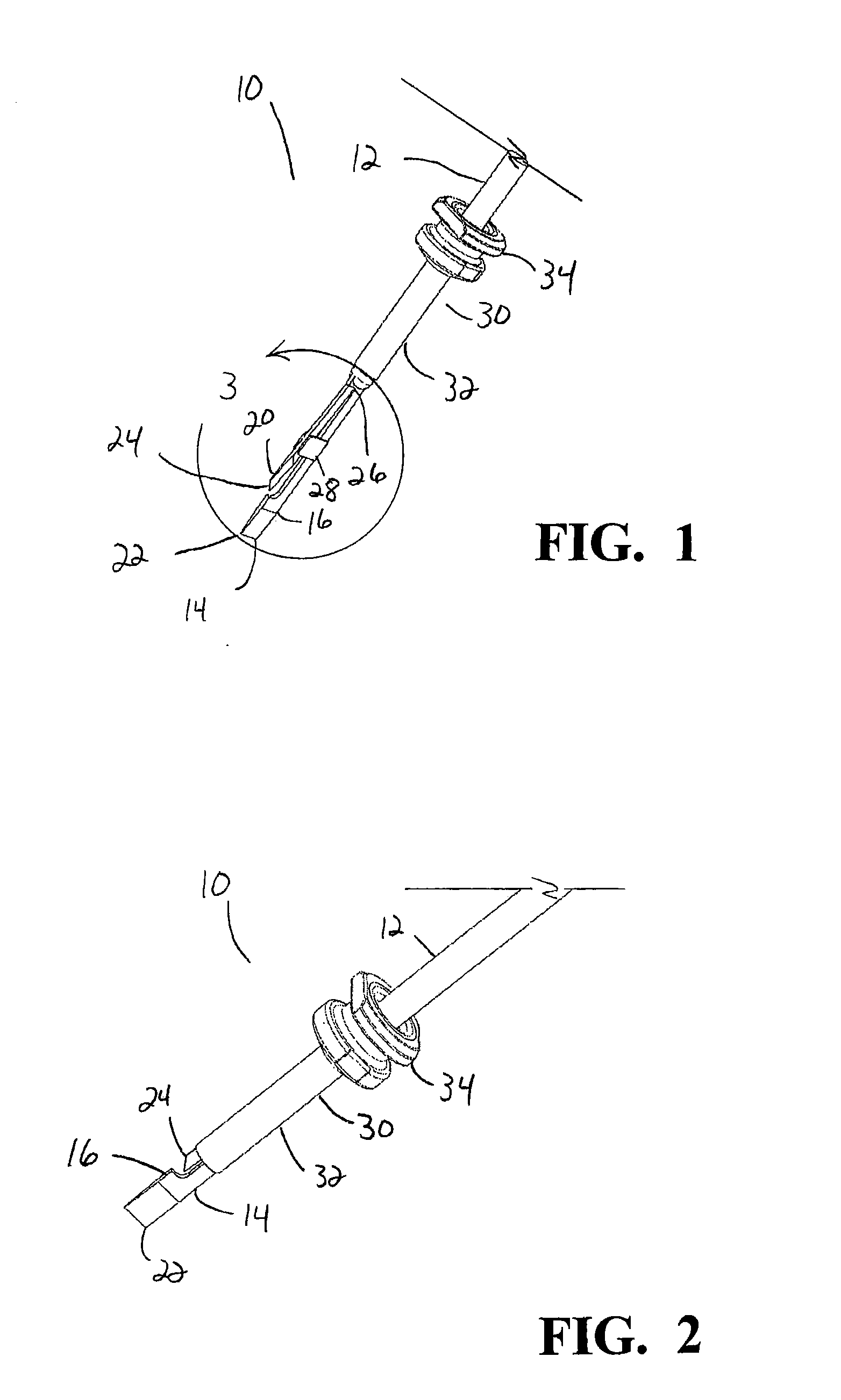
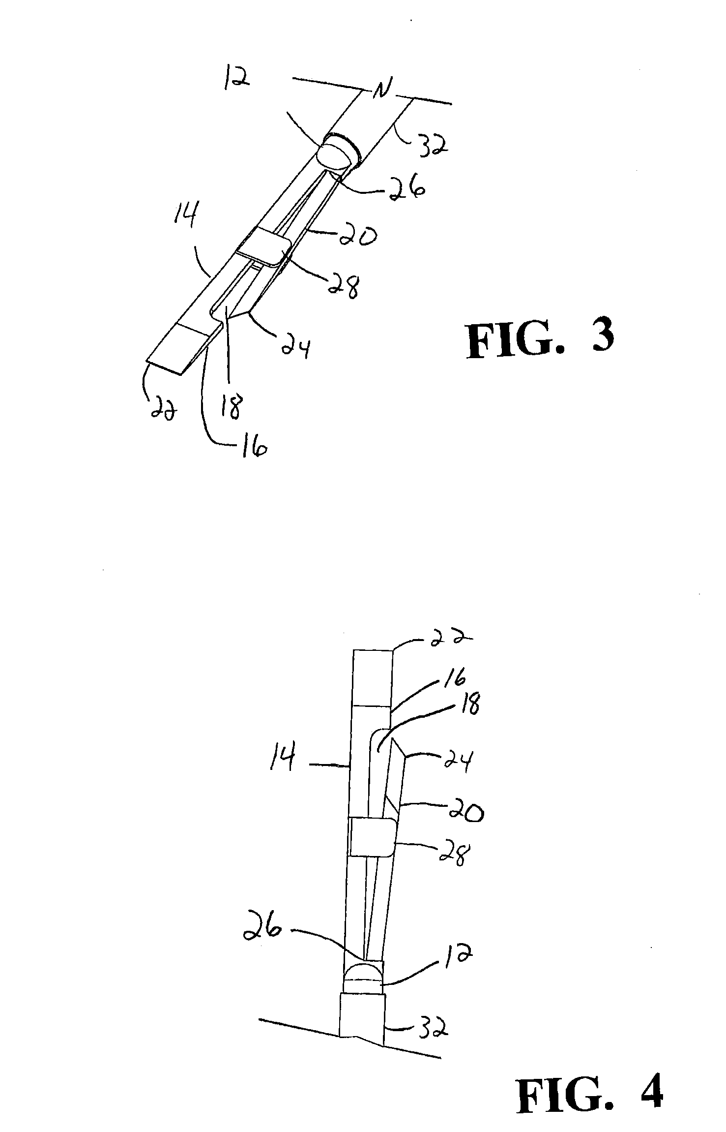
[0015]As best seen in FIGS. 1, 3 and 4, trocar 10 of the present invention generally consists of shaft 12 having blade 14. Blade 14 has two portions, fixed portion 16 having recess 18 and movable or extendable portion 20. Fixed portion 16 has sharpened edge 22 and movable portion 20 has sharpened edge 24. Both edges 22 and 24 are suitable for cutting or penetrating tissue such as ocular tissue. Fixed portion 16 and movable portion 20 are attached at spring hinge 26 that forces movable portion 20 out of recess 18 and away from fixed portion 16 in the relaxed or uncompressed state. As best seen in FIG. 2, when spring hinge 26 is compressed, movable portion 20 is forced within recess 18 of fixed portion 16. Blade guides 28 assist in keeping movement of movable portion 20 within the plane of blade 14.

[0016]In use, cannula 30 having tube 32 and hub 34 is slidably received on shaft 12 of trocar 10. Suitable cannulac 30 are well known in the art and are commercially available from Alcon La...


PUM


Abstract

A trocar having a blade split into two portions, a fixed portion and a movable portion. The movable portion is attached to the fixed portion at a pivot point that allows the movable blade portion to extend beyond the width of the fixed portion or be retracted within the width of the fixed portion. The cannula may be slidably received on the blade and provide the means to retract the movable portion of the blade to within the width of the fixed portion of the blade.

Description

[0001]This application claims the benefit of U.S. Provisional Application No. 61 / 020,235 filed Jan. 10, 2008.BACKGROUND OF THE INVENTION[0002]Microsurgical instruments typically are used by surgeons for any manipulations or removal of tissue from delicate and restricted spaces in the human body, particularly in surgery on the eye, and more particularly in procedures for manipulations or removal of the vitreous body, blood, scar tissue, or the crystalline lens. Such instruments may be hand-held, but often include a control console and a surgical handpiece with which the surgeon dissects, manipulates and / or removes the tissue. The handpiece has a surgical tool such as a vitreous cutter probe or an ultrasonic fragmentor for cutting or fragmenting the tissue and is connected to the control console by a long air pressure (pneumatic) line or power cable and by long conduits, cable, optical cable or flexible tubes for supplying an infusion fluid to the surgical site and for withdrawing or ...

Claims


Application Information

Patent Timeline
IPC IPC(8): A61B17/34
CPCA61B17/3417A61F9/00736A61B2017/32113
Inventor HICKINGBOTHAM, DYSON W.
Owner ALCON RES LTD
Why Eureka
Try Eureka