Cooling fan

a cooling fan and fan body technology, applied in the direction of machines/engines, stators, liquid fuel engines, etc., can solve the problems of many noise problems, and achieve the effect of changing the width

Inactive Publication Date: 2009-03-26
FU ZHUN PRECISION IND SHENZHEN +1
View PDF3 Cites 0 Cited by
  • Summary
  • Abstract
  • Description
  • Claims
  • Application Information

AI Technical Summary

Benefits of technology

[0007]In accordance with a preferred embodiment of the present invention, a cooling fan comprises a frame and an impeller having a plurality of blades disposed in the frame. The frame has a base and a sidewall extending from a periphery of the base with an air outlet defined therein. The base has an air inlet and a vent hole defined therein. The vent hole is in vicinity of the air outlet and between tip portions of the blades and the sidewall of the frame. In accordance with another preferred embodiment of the present invention, a cooling fan comprises a frame and an impeller having a plurality of blades disposed in the frame. The frame comprises a base and a sidewall extending from a periphery of the base with an air outlet defined therein. The base has an air inlet defined therein, a supporting portion disposed in the air inlet and two ribs extend from a periphery of the supporting portion towards the base so as to connect the supporting portion with the base. One of the ribs is arranged adjacent to the air outlet, and the one of the ribs arranged adjacent to the air outlet has a changeable width which is gradually increased along a direction from the supporting portion to the curved tongue portion.

Problems solved by technology

It is becoming a critical challenge on how to remove the heat so that the system can run reliably.
However, an air outflow in a curved tongue portion 16 of the frame 10 will interfere with the intake airflow of the air inlets 12, 14 and the later air outflow due to adverse airflow, creating many problems such as noise.

Method used


Image

  • Cooling fan
  • Cooling fan
  • Cooling fan

Examples


Embodiment Construction

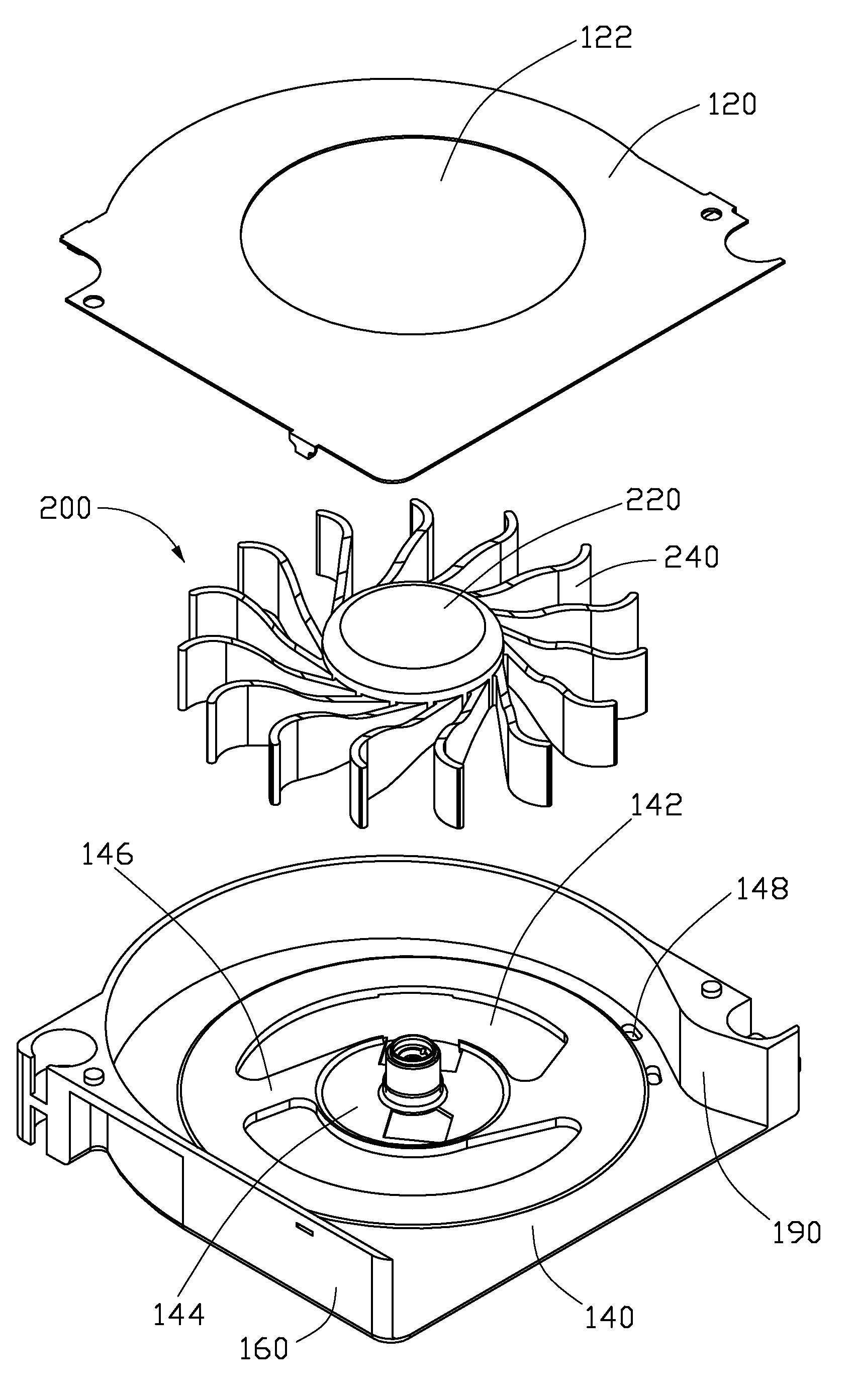
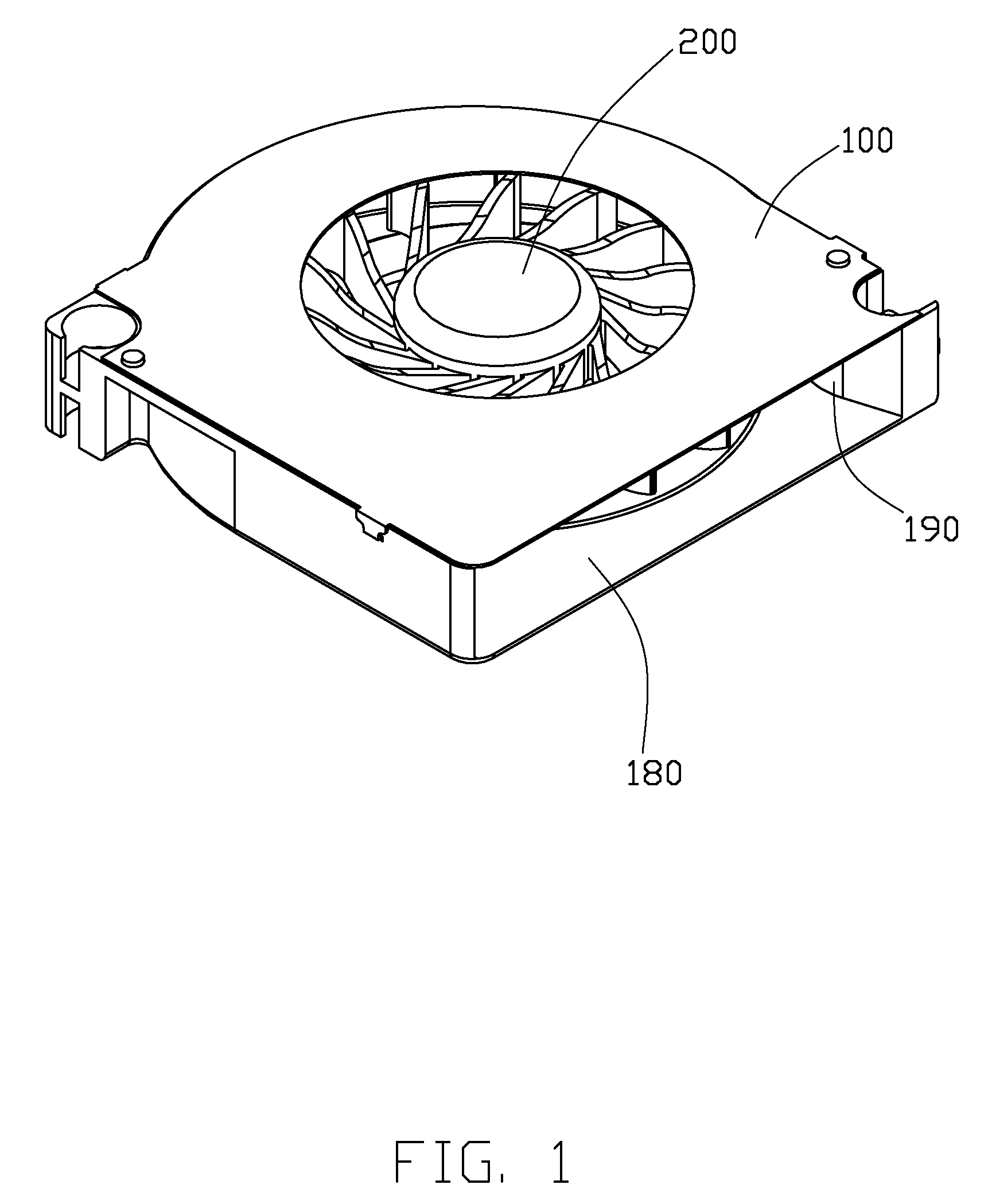
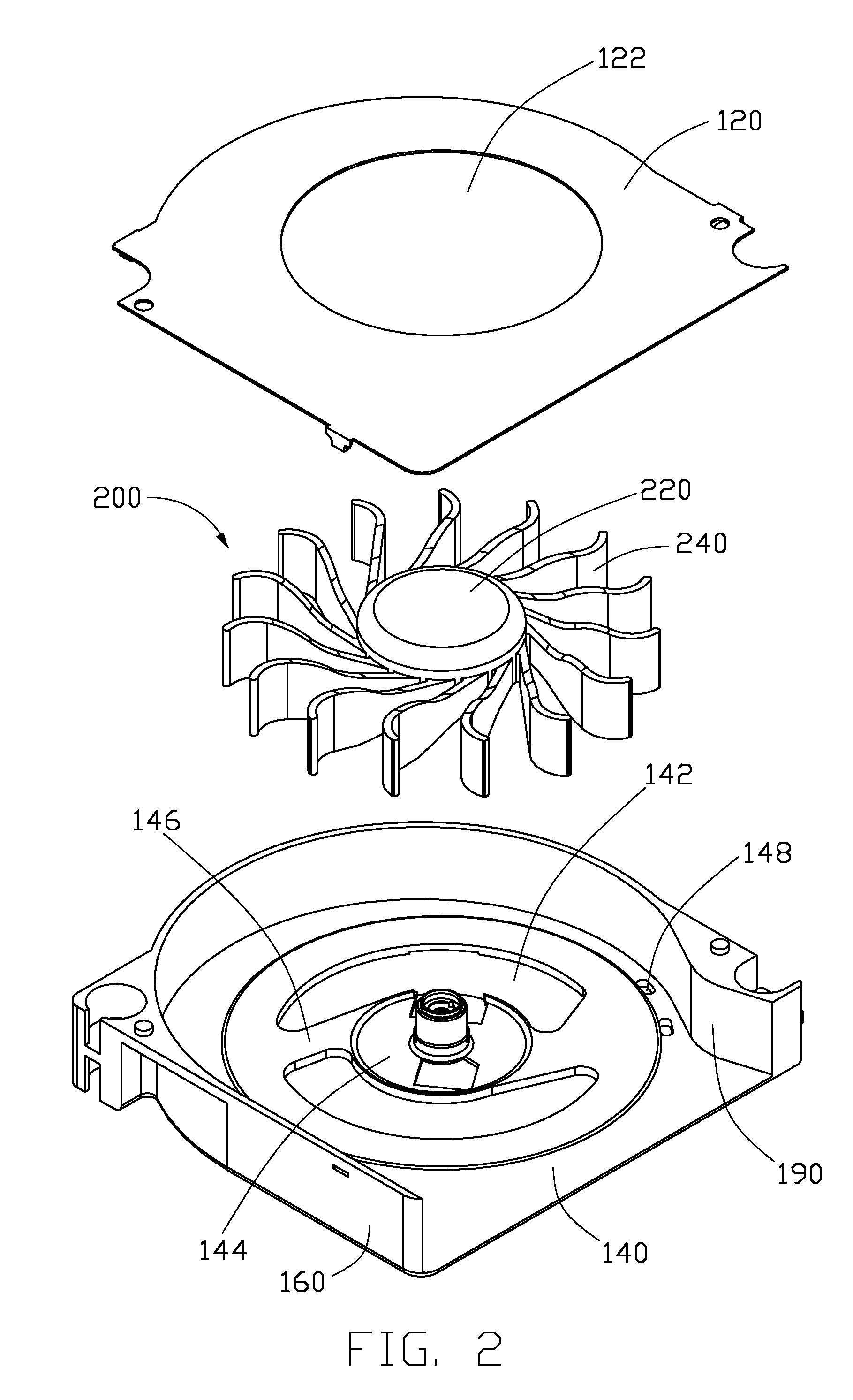
[0013]Referring to FIGS. 1-2, a cooling fan of a preferred embodiment of the invention comprises a frame 100, and an impeller 200 disposed in the frame 100. The impeller 200 comprises a hub 220 and a plurality of blades 240 mounted on the hub 220.

[0014]The frame 100 comprises a cap 120, a base 140, and a sidewall 160 perpendicularly and upwardly extending from a periphery of the base 140. The cap 120 is mounted on the sidewall 160 with a chamber formed between the cap 120, the base 140 and the sidewall 160. The impeller 200 is disposed in the chamber to blow an outward airflow out of the chamber from an air outlet 180, which is defined in a front of the sidewall 160. A curved tongue portion 190 protrudes inwardly from the sidewall 160, and is adjacent to the air outlet 180 to adjust airflow flowing into the frame 100.

[0015]The cap 120 and the base 140 respectively define a first air inlet 122 and a second air inlet 142 therein. The air enters into the chamber via the first and secon...


PUM


Abstract

A cooling fan includes a frame (100) and an impeller (200) with blades (240) disposed in the frame (100). The frame (100) has a base (140) and a sidewall (160) extending from a periphery of the base (140) with an air outlet (180) defined therein. The base (140) has an air inlet (142) and a vent hole (148) defined therein. The vent hole (148) is near the air outlet (180) and between tip portions of the blades (240) and the sidewall (160). In a preferred embodiment, the base (140) has a supporting portion (144) disposed in the air inlet (142). Two ribs (146) extend from a periphery of the supporting portion (144) towards the base (140). One of the ribs (146) is arranged adjacent to the air outlet (180) and has a changeable width which is gradually increased along a direction from the supporting portion (144) to the base (140).

Description

BACKGROUND OF THE INVENTION[0001]1. Field of the Invention[0002]The present invention relates generally to a cooling fan, and more particularly to a cooling fan having low noise.[0003]2. Description of Related Art[0004]The computer CPU speed has been greatly increased in recent years due to a rapid progress in semi-conductor technologies. The chip surface heat flux is thus higher and higher accordingly. It is becoming a critical challenge on how to remove the heat so that the system can run reliably. The compact space with high flow resistance in a notebook computer environment is even more critical in the heat removal. A fan with higher air pressure is frequently chosen under such a consideration.[0005]A fan in related art is shown in FIG. 3. The fan includes a frame 10 and an impeller 20 disposed in the frame 10. The frame 10 includes air inlets 12, 14 matching the impeller 20 and an air outlet. The impeller 20 includes a hub 22, a base plate 24 and a plurality of blades 26 formed...

Claims


Application Information

Patent Timeline
Patent Type & Authority Applications(United States)
IPC IPC(8): F04D29/54
CPCF04D17/08F04D29/4226F04D25/0613
Inventor HWANG, CHING-BAIZHAO, ZHI-HUIZHANG, JIE
Owner FU ZHUN PRECISION IND SHENZHEN
Why Eureka
Try Eureka