Reciprocating brace

a technology of reciprocating braces and stents, applied in the field of reciprocating braces, can solve the problems of debilitating fibrous adhesions and joint contractures, patient apprehension, pain, etc., and achieve the effect of promoting finger flexion and distance from a point on the patient's humeral area to the patient's fingers

Inactive Publication Date: 2009-07-30
M A R B REHAB INT
View PDF21 Cites 12 Cited by
  • Summary
  • Abstract
  • Description
  • Claims
  • Application Information

AI Technical Summary

Benefits of technology

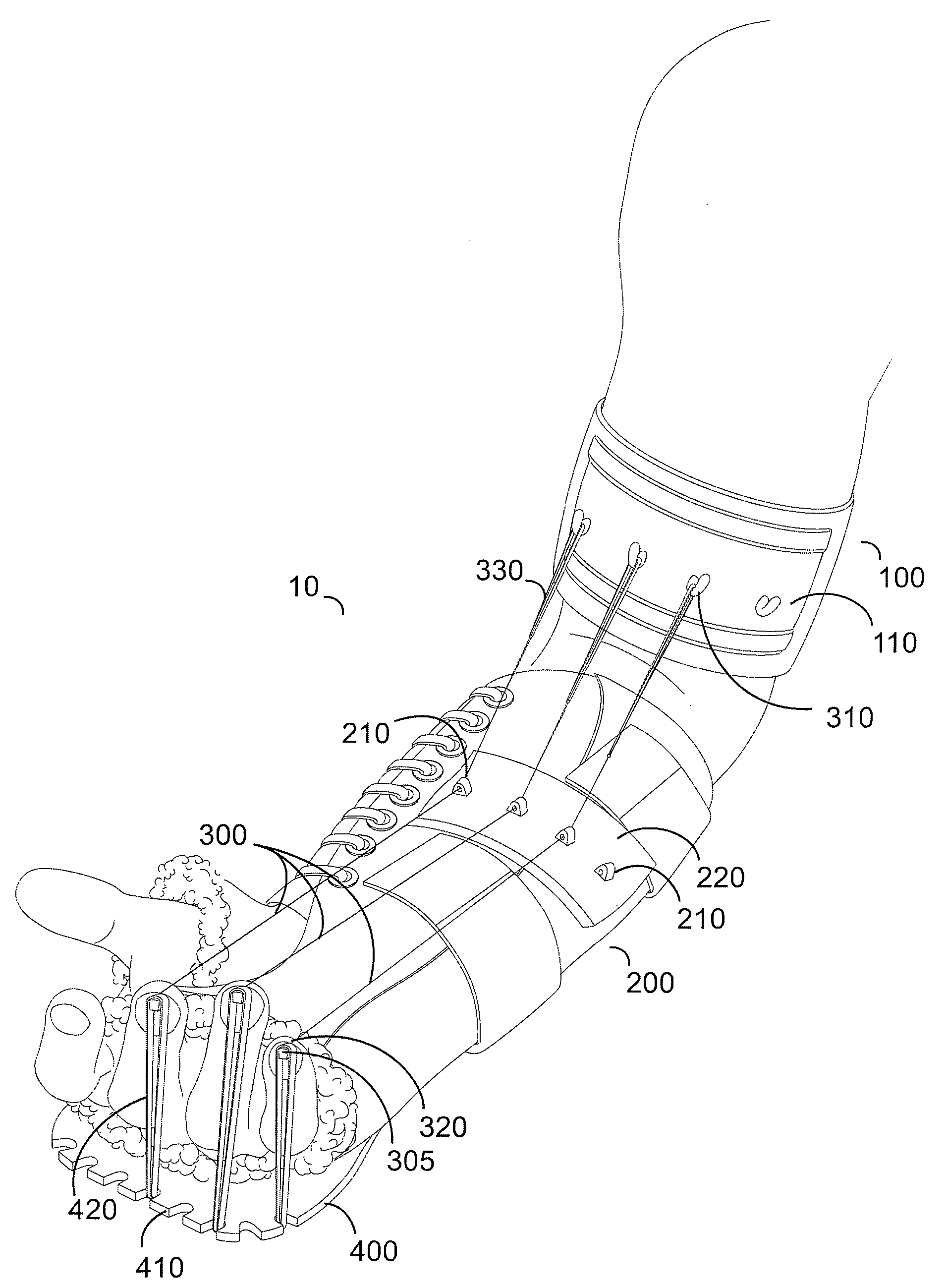
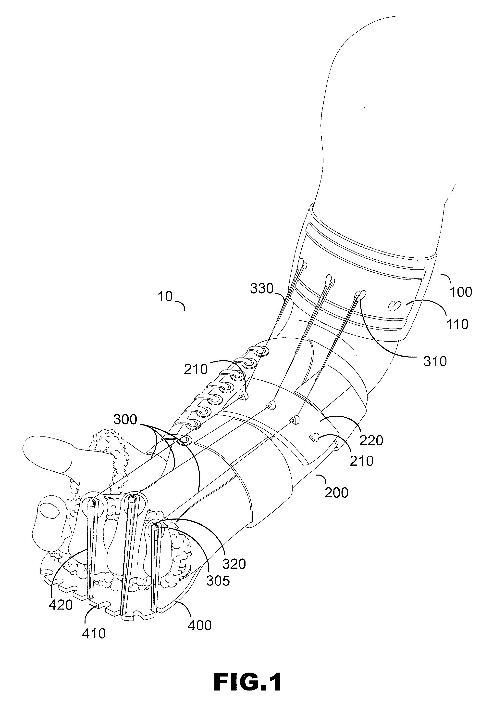
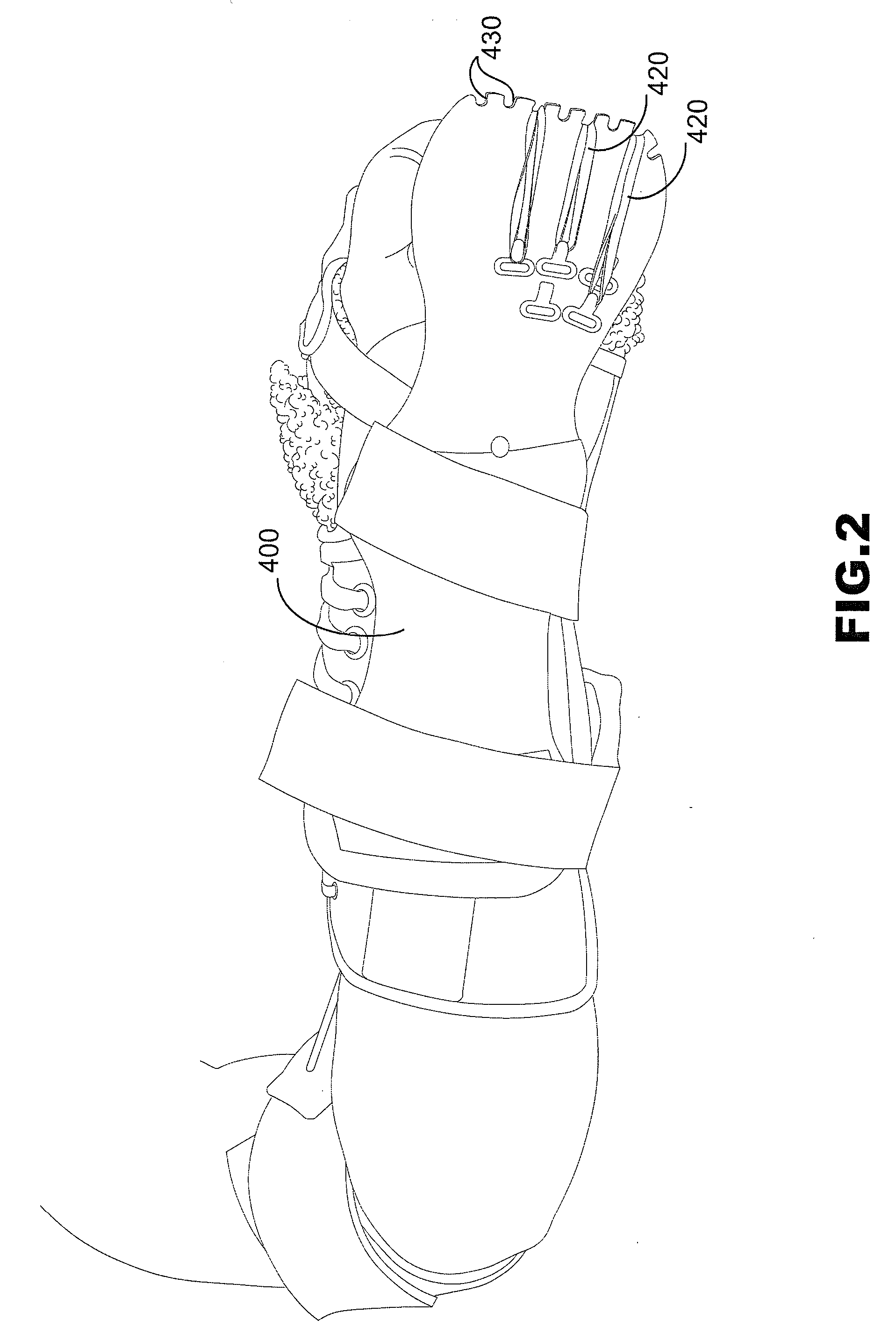
The invention describes a device used to treat patients with limited movement or mobility in their hands and feet. It uses pressure applied through a pneumatic system to promote blood flow and relax muscles in order to improve range of motion. By extending the patient's arms and measuring the gap between the shoulder and hand, the device can help move the fingers without causing discomfort or injury.

Problems solved by technology

The technical problem addressed in this patent text is the need for an apparatus that can assist in post-operative rehabilitation of finger joints by promoting flexion and contraction, while reducing stiffness and adhesions associated with surgery. The apparatus should be easy to use and inexpensive to manufacture.

Method used


Image

  • Reciprocating brace
  • Reciprocating brace
  • Reciprocating brace

Examples


Embodiment Construction

[0011]The present invention can be understood more readily by reference to the following detailed description, examples, drawing, and claims, and their previous and following description. However, before the present devices, systems, and / or methods are disclosed and described, it is to be understood that this invention is not limited to the specific devices, systems, and / or methods disclosed unless otherwise specified, as such can, of course, vary. It is also to be understood that the terminology used herein is for the purpose of describing particular aspects only and is not intended to be limiting.

[0012]The following description of the invention is provided as an enabling teaching of the invention in its best, currently known embodiment. To this end, those skilled in the relevant art will recognize and appreciate that many changes can be made to the various aspects of the invention described herein, while still obtaining the beneficial results of the present invention. It will also...


PUM


Abstract

An apparatus for passive contraction of at least one finger of a patient with an upper arm unit, a lower arm unit, and at least one connective line. The apparatus is configured such that elbow extension of the patient promotes finger flexion. This is accomplished by taking advantage of the geometry of the arm, where the distance from a point on the patient's humeral area to the patient's fingers is greater when the patient's arm is in extension than when it is in flexion. In one aspect, the upper arm unit is configured to connect to a portion of the patient's arm between the patient's elbow and shoulder and the lower arm unit is configured to connect to a portion of the patient's arm intermediate the patient's hand and elbow.

Description


Claims


Application Information

Patent Timeline
Owner M A R B REHAB INT
Why Eureka
Try Eureka