Time limited restraint

a time-limited restraint and time-limited technology, applied in the field of time-limited restraint, can solve the problems of unit leader's difficult choice, inacceptable to the forces of most civilized countries, and his or her death

Active Publication Date: 2009-08-27
BUTLER FRANK +2
View PDF30 Cites 21 Cited by
  • Summary
  • Abstract
  • Description
  • Claims
  • Application Information

AI Technical Summary

Problems solved by technology

A problem is the chance encounter with an individual who is, or appears to be, a non-combatant.
If the individual is taken into custody, the unit leader faces a difficult choice.
The captive could be killed to prevent this scenario, but this choice is not acceptable to forces of most civilized countries.
This avoids the act of killing the prisoner, but might result in his or her death if not discovered within a reasonable time.
Taking the prisoner with the patrol presents the patrol with a great risk of compromise should the prison

Method used


Image

  • Time limited restraint
  • Time limited restraint
  • Time limited restraint

Examples


Embodiment Construction

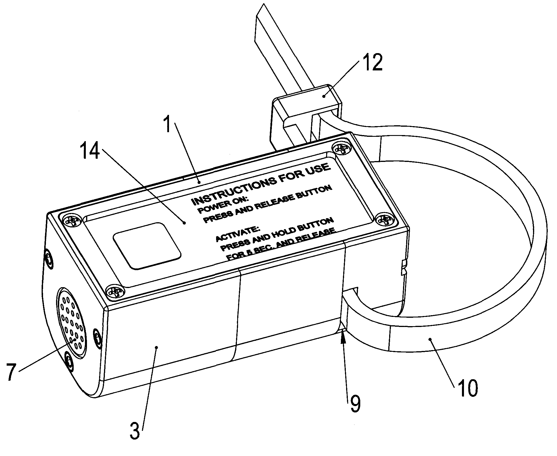
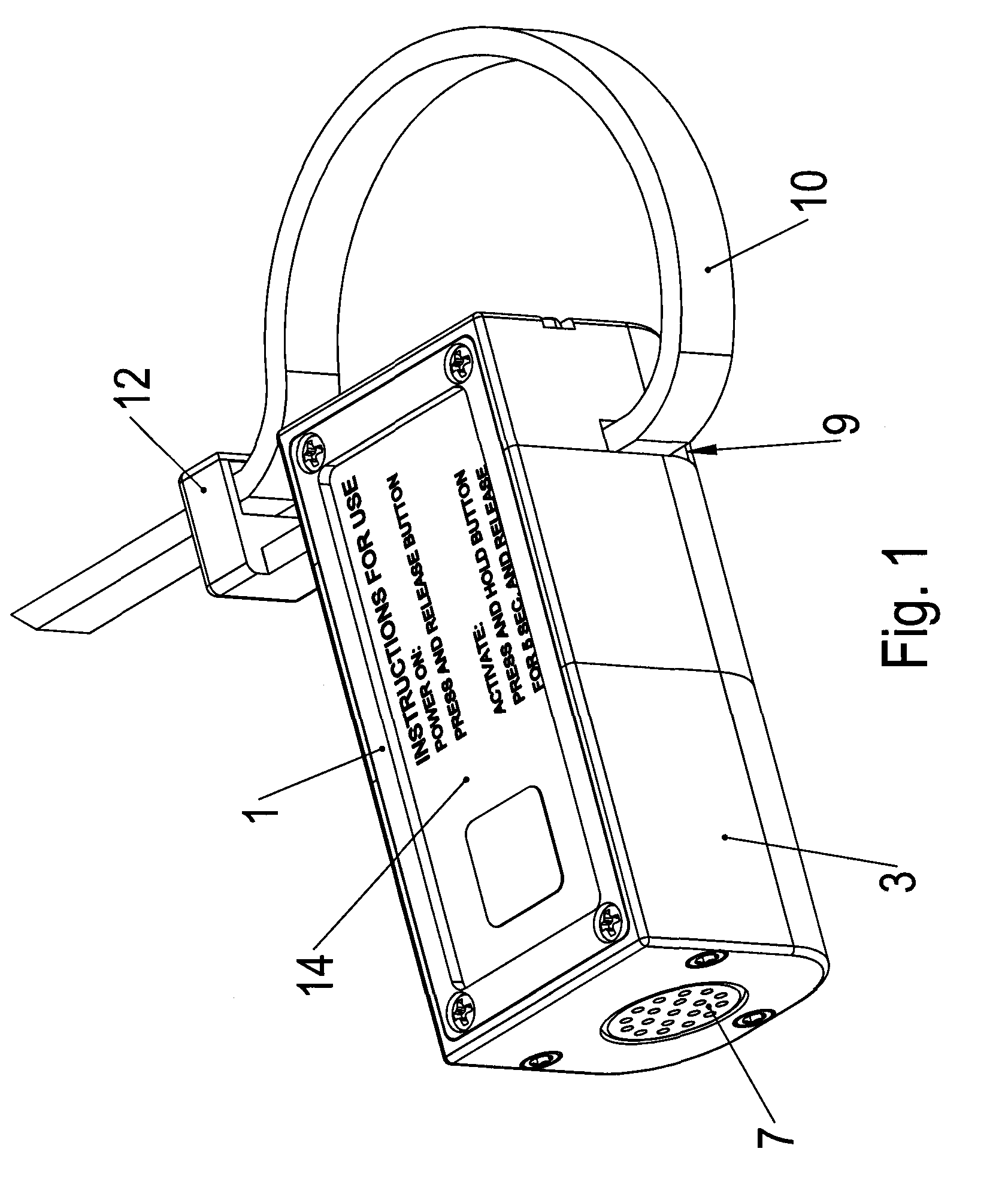
[0010]FIG. 1 shows a housing 3 of an embodiment of the restraint device. A restraint 10 is inserted through a receiving opening that forms a restraint guide 9 in an end of the housing. The restraint 10 may be a ratcheting type restraint. One end of the restraint of a preferred embodiment passes through an opening in the restraint, and the end may be easily pulled to tighten the restraint. However, the ratcheting mechanism or attachment member 12 makes it very difficult to pull the restraint in the opposite direction. The restraint is an elongated member that is sufficiently flexible to pull through the receiving opinion in the restraint guide 9 and sufficiently flexible to wrap around both wrists and / or both ankles of a person to be restrained.

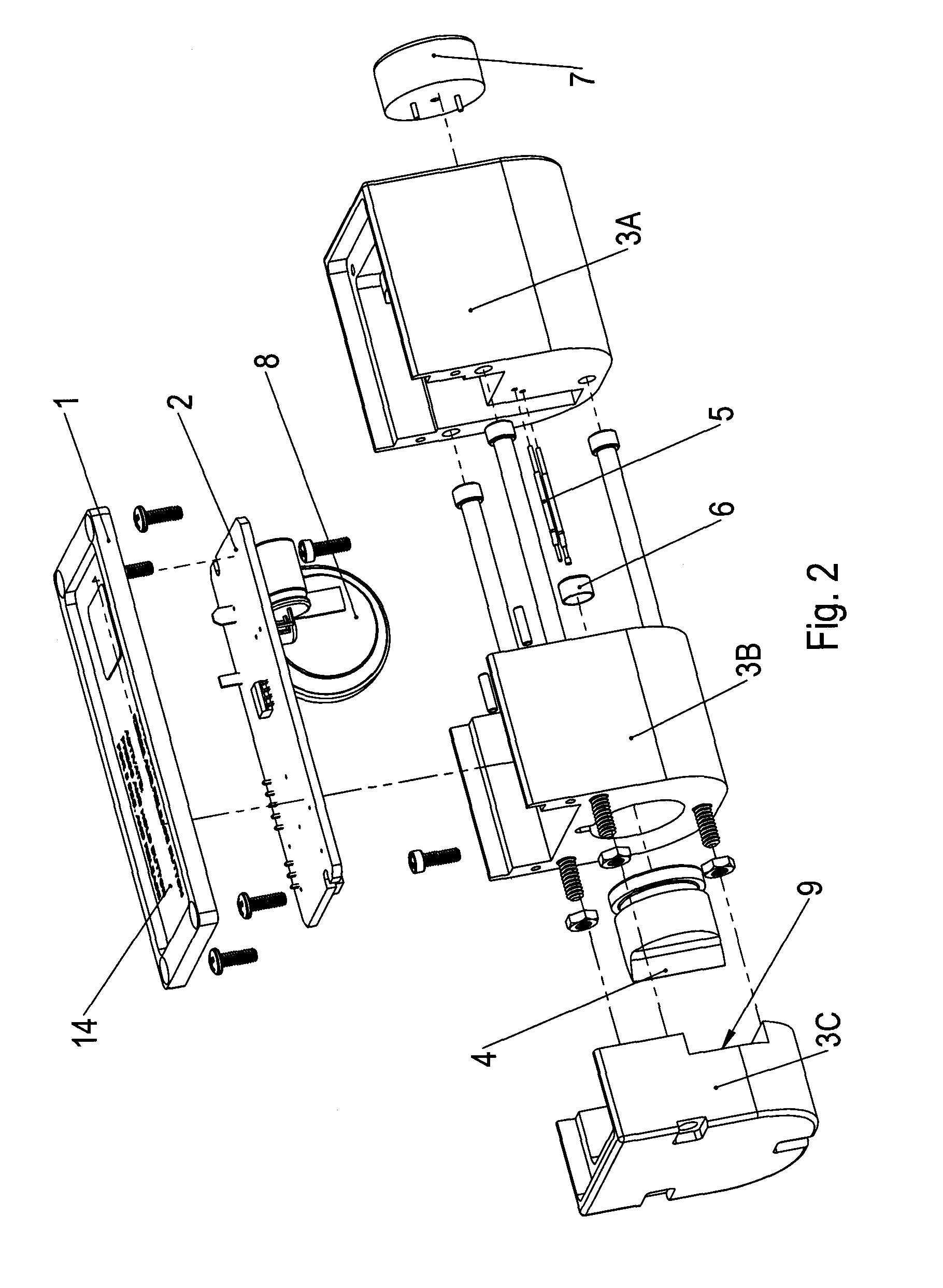
[0011]Components of an embodiment of the device are demonstrated in FIG. 2. The housing 3 may be formed in three (3) parts, which are designated in FIG. 2 as 3A, 3B and 3C. An interface panel 1 covers a central processing unit (CPU) 2 that con...


PUM


Abstract

A time limited restraint device. After a predetermined time, a cutter of the time limited restraint device cuts a restraint.

Description

[0001]Applicants claim the benefit of provisional application Ser. No. 61 / 031,447 filed Feb. 26, 2008, and provisional application Ser. No. 61 / 077,305 filed Jul. 1, 2008 and provisional application Ser. No. 61 / 111,017 filed Nov. 4, 2008.BACKGROUND OF THE INVENTION[0002]Combatants, such as Special Operations units, are called upon to conduct operations in hostile areas with little or no support immediately available. In these circumstances, the survival of the team often depends primarily on remaining undetected. A problem is the chance encounter with an individual who is, or appears to be, a non-combatant. If the individual is taken into custody, the unit leader faces a difficult choice. If released, the individual would likely reveal the presence of the combatants. The typical result from this sequence of events is an engagement in which the unit may be overwhelmed by a superior force. The captive could be killed to prevent this scenario, but this choice is not acceptable to forces...

Claims


Application Information

Patent Timeline
IPC IPC(8): E05B75/00E05B51/00E05B43/00E05B47/00E05B17/00E05B39/00
CPCE05B43/00Y10T24/1498G09F3/0329E05B75/00Y10T70/7062Y10T70/625Y10T70/7051Y10T70/704Y10T70/80Y10T70/404Y10T70/8027
Inventor BUTLER, FRANKRUSHER, WILLIAM G.UFKES, PHILIP J.
Owner BUTLER FRANK
Why Eureka
Try Eureka